background image

- 85 -

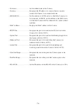
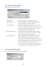
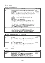
• Activation Mode ................... Used to set the output mode of the external GP10 output

terminal.

Normal Open...................... Closes the contact during output to keep continuity.

Normal Close ..................... Opens the contact during output.

(19) Camera Settings (AE Settings)

For each setting item, see the description of each function on page 59.

(20) Camera Settings (Picture Settings)

For each setting item, see the description of each function on page 61.

Summary of Contents for PTC-401CIP

Page 1: ...Please read this instruction manual carefully before using PTC 401C IP and keep it for future reference PAN TILT ZOOM COLOR CAMERA PTC 401C IP INSTRUCTION MANUAL...

Page 2: ...eriods of time 11 Refer all servicing to qualified personnel Servicing is required when the apparatus has been damaged in any way such as power supply cord or plug is damaged liquid has been spilled o...

Page 3: ...erence in which case the user will be required to correct the interference at his own expense USER INSTALLER CAUTION Your authority to operate this FCC verified equipment could be voided if you make c...

Page 4: ...he sun or the camera may be damaged This Camera is designed only for installation to the ceiling When installing this Camera use only the dedicated fixing plate refer to the pages 11 to 15 of this man...

Page 5: ...eof without the right holders prior consent The filming of demonstrations performances exhibits etc may be restricted even for the purpose of monitoring All copyrighted images and data may be used wit...

Page 6: ...9 5 THE ID NUMBER REMOTE ID SETTING 20 6 SETTING IN THE OSD ON SCREEN DISPLAY MENU 21 7 Alarm 29 8 RS 485 30 1 Setting the terminating resistance 30 2 Setting the ID address 30 9 SOUND 31 10 SETTING O...

Page 7: ...Settings 70 6 MPEG4 Setup 71 7 JPEG Setup 72 8 Network Setup 73 9 Alarm Setup 75 10 E mail Setup 76 11 FTP Setup 77 12 Motion Detection Setup 79 13 User Setup 80 14 IP filtering Setup 82 15 Snapshot...

Page 8: ...ASE ORNAMENTAL RING CAMERA HEAD INFRARED SENSOR LENS VIDEO OUT TERMINAL BNC jack DC IN COMPOSITE CABLE ALARM IN OUT TERMINAL 6P connector Black RS 485 TERMINAL 5P connector White AUDIO OUTPUT Green AU...

Page 9: ...point automatically to maintain it in the P 18 in focus status NEAR To move the focal point near P 18 FAR To move the focal point far P 18 TELE To zoom in TELE the image P 17 WIDE To zoom in WIDE the...

Page 10: ...ay not receive them at all depending on the ambient environment such as being placed under the sunlight or near an inverter fluorescent lamp In such case relocate the installation place of the receivi...

Page 11: ...use in initially confirming the operation of the Camera It is not guaranteed that these batteries will work effectively for the indicated period When multiple Cameras are operated through the wireles...

Page 12: ...trong enough to hold the total mass of the main unit and fixing plate If not the Camera could fall causing injury 1 Mounting the Fixing Plate 1 Make mounting holes and a cord hole in the place ceiling...

Page 13: ...the Fixing Plate 1 Match the mark on the fixing plate with the mark on the back face of the main unit set the tabs 3 locations of the back face of the main unit in the mating cuts 3 locations of the f...

Page 14: ...d 3 Mounting the Safety Wires 1 Loop up one end of the Safety Wires through the respective safety wire looping holes made on the Ceiling Plate and then loop up the other end of the same around the bea...

Page 15: ...ied SET SCREW M3 5 1 PCE supplied 2 Drawing the Composite Cable from the Camera Back Face 1 Cut off the blank cover from the back face of the Camera base with pliers or the like and draw the composite...

Page 16: ...E supplied PC POWER CABLE supplied Speaker with amplifier Brown Red Orange Yellow Green 1 2 3 4 5 DATA IN DATA IN DATA OUT DATA OUT GND Pin No Terminal Name Cord Color Blue Gray White Black Pink 1 3 4...

Page 17: ...Camera power is turned OFF automatically upon the lapse of the set time 3 1 1 2 Turning ON the Camera When the Camera is OFF and POWER button is pressed the Camera power is turned ON The image appear...

Page 18: ...e screen when TELE button of ZOOM is pressed or zoomed out appears smaller in the screen when WIDE button of ZOOM is pressed When TELE button or WIDE button is held down for over one second the zoom s...

Page 19: ...EAR button or FAR button When NEAR button is pressed the focus shifts near to you When FAR button is pressed the focus shifts far away from you 12 11 12 11 10 3 Iris The iris remains in the AUTO IRIS...

Page 20: ...gistration of the preset contents is completed The preset contents already registered if any are overwritten The home position can be registered freely to any position by using the preset No 0 4 2 2 2...

Page 21: ...era can be operated via the wireless remote controller 4 3 3 17 3 Canceling the specific ID of the Cameras Hold down ID button for over 2 sec and the blinking LED on the Camera will light up Then unha...

Page 22: ...PAN TILT operation press CURSOR PAN TILT button To resume the menu operation press CURSOR PAN TILT button again 18 18 16 15 17 17 1 MAIN CONTROL Name Factory Settings Function To turn ON OFF the char...

Page 23: ...ver this set time with no operation after the PAN TILT ZOOM operation the Camera will return automatically to the home position The home position can be registered freely with the preset No 0 To set t...

Page 24: ...tion is used with this function in the OFF status the image could be out of focus 6 INFRARED OFF To set the maximum number of fields of the low speed shutter 2fields 3fields 4fields 5fields 6fields 8f...

Page 25: ...lance Setting mode ATW AWC INDOOR OUTDOOR FL LIGHT MWB WB AREA0 AREA4 AREA2 AREA3 AREA1 4 To select the image area of the object that needs an appropriate brightness and weighing according to the sele...

Page 26: ...o set the blue color tendency 30 30 when MWB is selected To select ON OFF of the masking function When there is any part to be masked in the image to be captured this function masks such part However...

Page 27: ...mask any confidential information by using this function To register the Camera main unit name This function is convenient when multiple Cameras are used Move the cursor to CAMERA to make the cursor b...

Page 28: ...C40SM both available on option is attached set this function to ON According to the dome cover this function limits the TILT operation range When the dome cover is not attached set this function to OF...

Page 29: ...When this function is set to ON as long as the input is in the ALARM IN terminal 1 other operations are disabled Set this function to ON OFF OFF When the rotation angle exceeds 90 the Camera is facing...

Page 30: ...28 Note Another set alarm action takes place caused by alarm input 1 or 2 takes place after moving to corresponding preset number 1 or 2 Note Since a preset action does not take place when a motion is...

Page 31: ...ellow Green 1 2 3 4 5 Signal Name DATA DATA DATA DATA GND Signal Function side To input the transmitted received data side To input the transmitted received data side To output the transmitted receive...

Page 32: ...und on page 69 Note When dedicated software for MPEG4 is used for the connection between a client and the Camera no sound will be transmitted or received if you select MPEG4 Setting Frame Rate page 46...

Page 33: ...itializing the settings Set DIP switch No 2 to ON to turn ON the power In ten seconds all of the PAN TILT settings lens settings preset settings OSD on screen display based Camera settings and network...

Page 34: ...in the server and transmitting e mail by alarm input IP filtering function For restricting hosts permitted to access the Camera Note The Camera is not connectable to some network systems Note Some res...

Page 35: ...twork whose IP address is 192 168 1 10 you cannot connect the Camera to the network and make settings In this case it is necessary to configure a network of 192 168 1 0 comprising the Camera and a hos...

Page 36: ...or more commercially available Note As soon as a network unit is connected to its Ethernet terminal the Camera automatically adjusts and sets the 10BASE T 100BASE TX and half duplex full duplex commu...

Page 37: ...been installed DirectX is contained in the Viewer install program on the CD ROM Install it according to the instructions of the Viewer Install wizard Installing Viewer Install Viewer by running the EL...

Page 38: ...ewer will be uninstalled 3 Web browser 1 Restrictions Access to the Camera via a Web browser requires the PC to meet the following requirements Microsoft Windows 2000 or XP JRE Java Runtime Environmen...

Page 39: ...r 1 Enter http at Address D 2 When the IP address or host name of the Camera is assigned enter the host name and put at the end Example Since the IP address of the Camera set by the factory is 192 168...

Page 40: ...ay information in Japanese the browser must be capable of properly displaying Japanese pages 5 The main page is displayed Home Displays the main page Setup Displays the Setup screen Live View Half D1...

Page 41: ...of 160 120 Capture View Half D1 Displays capture images with a size of 704 480 Capture View SIF Displays capture images with a size of 352 240 Capture View QQVGA Displays capture images with a size of...

Page 42: ...IF 352 240 QQVGA 160 120 Note Half D1 displays 704 x 240 images in the size of 704 x 480 Example Live View SIF 352 240 q PAN TILT By sliding the scroll bar or clicking on Camera Position the image mov...

Page 43: ...ide The object is displayed small Tele The Tele side The object is displayed large iIris Adjusts the iris The auto iris the automatic adjustment function to keep brightness at the same level even if t...

Page 44: ...n the size of 704 x 480 Example Capture View SIF 352 240 How to save snapshots 1 Click the right mouse button on the image 2 Select Save Image As from the menu 3 The image to be saved appears Set a lo...

Page 45: ...ting to the Camera You can jump to pages on which settings for the Camera can be made To go to each setup page click on the corresponding link on the screen shown below Note You must log in with the a...

Page 46: ...set the activation mode of the external GPIO Activation Mode Used to set the output mode of the external GPIO output terminal Normal Open Close the contact during output to keep continuity Normal Clo...

Page 47: ...range 64 to 2000 kbps Framerate Designate the number of frames to be displayed per second setting range 30 15 10 5 and 1 frames second Note Sound will not be received or transmitted when 1 is set at...

Page 48: ...ate image quality High High image quality Although high quality images can be obtained the load on the transmission line increases Normal Medium image quality with a compression rate between High and...

Page 49: ...ote Before making network settings consult the administrator of the network you are going to use Note If this item is changed the connection setting for the Camera may need to be changed In this case...

Page 50: ...a to an external network DNS1 DNS2 Set the address of a DNS server to which the Camera is to be connected At DNS2 set the address of the DNS server to which the Camera will be connected if it cannot c...

Page 51: ...Use one byte alphanumerical characters Alarm 1 2 Motion Detection Action Select the action of the alarm when an alarm signal is input to the alarm input terminal None No action will take place Send FT...

Page 52: ...2 MotionDetectionAlarmOut Set whether to give alarm output when a motion is detected 11 E mail Setup Make settings relating to e mail To Designate the address to which e mail will be transmitted From...

Page 53: ...smitting e mail Note Two byte characters including Japanese characters are not available for a message Use one byte alphanumerical characters Action Select what to be sent when transmitting e mail Tex...

Page 54: ...ore Set whether to regularly transmit and save images in the FTP server Time Store login each send Set whether to connect to the FTP server each time images are transmitted or not always connected Tim...

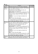
Page 55: ...strator The login ID is fixed to root With this ID you can view images operate the Camera and make settings Operator You can view images and operate the Camera User You can only view images Only root...

Page 56: ...istered data is displayed in the input area Change the item s you desire and click on the Modify button Note With regard to root only the password can be changed Deleting a user You can delete the reg...

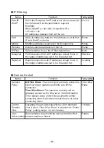
Page 57: ...ddresses shown in Exception List Only connections from the IP addresses contained in the client list will be rejected Reject all Rejects all clients attempting to connect to the Camera It can be conne...

Page 58: ...t made the authority of the client becomes operator In this case the Setting screen displays the Authentication window Enter the ID and password of the administrator Control Policy Designate the mode...

Page 59: ...iod for which motion detection is prevented after the Camera performs PAN TILT ZOOM when the motion detection function is enabled and a detection area is set setting range 1 to 10 seconds 16 Camera Se...

Page 60: ...he object becomes dark PRIORITY To set the maximum gain of the AGC 0dB 4dB 8dB 16dB 20dB 24dB The AGC is a function of amplifying the signal from the CCD to make the object visible when the object bec...

Page 61: ...60 18 Camera Settings Picture Settings By clicking on an item the corresponding setting screen appears The selected item is displayed here...

Page 62: ...de ATW AWC INDOOR OUTDOOR FL LIGHT MWB WB AREA0 AREA4 AREA2 AREA3 AREA1 To select the image area of the object that needs an appropriate brightness and weighing according to the selected area HIST To...

Page 63: ...doors The color temperature is assumed to be 6300K OUTDOOR This function is selected when the Camera is used under the fluorescent illumination The color temperature is assumed to be 4200K FL LIGHT To...

Page 64: ...ction is set to ON the image during the movement between the preset positions becomes static the image before the movement In this mode movement is enabled between the preset positions including the h...

Page 65: ...64 20 System Time Setup Set the internal clock of the Camera The time of this clock will be added to the file name when sending an E mail or FTP...

Page 66: ...tion of Viewer in all environments 2 Connection At the time of the initial startup 1 Run the Viewer program and a window for registering a Viewer ID and a password appears Register your ID and passwor...

Page 67: ...wrong login ID or password three times the program will be exited 2 Viewer s main screen is displayed 3 Select Camera Connect and the Connect Dialog screen appears 4 Enter the IP address login name ID...

Page 68: ...ormer display when double clicking it again Obtaining snapshots You can save snapshots which are in sizes of Half D1 SIF and QQVGA on the Camera in a specific folder Select Still from the menu bar or...

Page 69: ...ove PAN TILT takes place at designated intervals of move according to the setting of Step each time the button is pressed Speed The operating speed of PAN TILT can be set setting range 1 to 15 Step Th...

Page 70: ...on saved by the Camera and the actual position match each other Preset Control This function is available when Time Slice Share is set for Control Policy in camera control setup page 87 and opens the...

Page 71: ...rophone button in the Viewer menu or the icon on the icon bar clicked on the loudspeaker with an amplifier connected to the Camera outputs it No sound will be output from the loudspeaker with an ampli...

Page 72: ...range 64 to 2000 kbps Frame Rate Designate the number of frames to be displayed per second setting range 30 15 10 5 and 1 frames second Note Sound will not be received or transmitted when 1 is set at...

Page 73: ...ate image quality High High image quality Although high quality images can be obtained the load on the transmission line increases Normal Medium image quality with a compression rate between High and...

Page 74: ...host for connection Up to 3 addresses can be connected from Viewer to the Camera Multicast UDP Image data is distributed irrespective of whether the Camera is connected or is not connected from the h...

Page 75: ...ignate the port to be used for the Web server for the Camera 80 1024 to 65535 Option Port Designate the port to be used for distributing images from the Camera 1024 to 65535 Multicast Port Designate t...

Page 76: ...signal is input to the alarm input terminal None No action will take place Send FTP The JPEG file of the obtained snapshot will be transferred by FTP Send E Mail E mail will be transmitted Both The J...

Page 77: ...ting e mail Text Only Only a text will be sent when e mail is transmitted Picture Only Only an image will be sent when e mail is transmitted Both Both a text and an image will be sent when e mail is t...

Page 78: ...gnated account name User ID Designate an account name for connection to the FTP server to which the FTP will be transmitted User PW Designate a password for the account name shown above Passive Mode D...

Page 79: ...in the directory for saving the data of the older file will be overwritten Designate a different file name Note Two byte characters including Japanese characters are not available for a file name to b...

Page 80: ...itivity Set the sensitivity of motion detection Area settings When Select under Tools is checked the area on the screen that is selected by drag drop will be set for a motion detection area When Delet...

Page 81: ...gin ID is root that is unchangeable With this ID you can view images operate the Camera and make settings Operator You can view images and operate the Camera User You can only view images Only root ca...

Page 82: ...gistered data is displayed in the input area Change the item s you desire and click on the Modify button Note With regard to root only the password can be changed Deleting a user You can delete the re...

Page 83: ...e IP addresses contained in the client list will be rejected Reject All Rejects all clients attempting to connect to the Camera It can be connected from the IP addresses shown in Exception List Only c...

Page 84: ...snapshots You can refer to folders with the Browse button File name Designate a file name to be saved Enable Overwrite Enables the overwrite of the last saved snapshot when saving a new snapshot with...

Page 85: ...cting client Control Duration Time Designate the period during which a client maintains control when Time Slice Share is selected at Control Policy setting range 1 to 60 minutes User Authentication Se...

Page 86: ...ses the contact during output to keep continuity Normal Close Opens the contact during output 19 Camera Settings AE Settings For each setting item see the description of each function on page 59 20 Ca...

Page 87: ...isc Settings For each setting item see the description of each function on page 63 22 System Time Setup Set the internal clock of the Camera The time of this clock will be added to the file name when...

Page 88: ...play Mode Displays the image in the entire window irrespective of the image s aspect ratio Import Setup Data Enables you to set on the Camera set values saved in the PC available only when the Camera...

Page 89: ...e firmware for firmware updating that was distributed by the shop where you purchased the product or our branch or sales office nearby Using another firmware or modified firmware may cause the Camera...

Page 90: ...connection or any of the network settings is incorrect Reconfirm the connection between the Camera and the host and the network settings 9 After the firmware is updated properly the Camera completes g...

Page 91: ...s Password Set a password for the ID root You can use up to 16 one byte characters for a password including alphanumerical characters and upper case and lower case alphabetic characters ELMO 1Channel...

Page 92: ...Designate the size of images to be displayed D1 D1 704 x 480 SIF 352 x 240 Mode Set a delay for images according to the network frame environment Frame Reduces the delay for images GOP Enables live im...

Page 93: ...dress of the DNS server to which the 0 0 0 0 Camera will be connected if it cannot connect to DNS1 Subnet Set the subnet mask address of the Camera 255 255 mask 255 0 Broadcast Set the broadcast addre...

Page 94: ...l be transmitted at the same time Matched Designate the size of JPEG images to be attached SIF Resolution when transmitting the FTP or transmitting e mail as Alarm 1 set at Alarm 1 Action Half D1 SIF...

Page 95: ...be transmitted Both The JPEG file of the obtained snapshot will be transmitted by FTP and e mail will be transmitted at the same time Matched Designate the size of JPEG images to be attached SIF Reso...

Page 96: ...ther to use user authentication on the None Authentica SMTP server to be used tion POP before Designate whether to use POP before SMTP on the None SMTP SMTP server to be used User ID Set a login ID fo...

Page 97: ...ansmitting the FTP Use passive mode when there are restrictions on the ports because of a firewall etc Time Store Set whether to regularly save images in the FTP server None Time Store Set whether to...

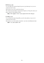
Page 98: ...cluding alphanumerical characters and upper case and lower case alphabetic characters Modifying a You can modify the registered login ID password and user authority of any user for connection to the C...

Page 99: ...et in the Exception list Reject all Rejects access from all IP addresses except those in Invalidity the range of addresses set in the Exception list Camera Control Name Function Factorysettings Camera...

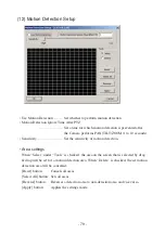
Page 100: ...detection High High adjustable using the scroll bar Low Set Clear Used to select Set or Clear Set Set Sets the area dragged on the screen as a detection area Clear Sets the area dragged on the screen...

Page 101: ...n the TELE side and imaging a dark P 17 monochromatic object Isn t the LED lighting in red If yes the Camera power P 16 should be OFF Isn t the OFF TIME function activated turning OFF the P 16 Camera...

Page 102: ...disabled B W image This Camera has the B W color switching function P 23 Check the settings No switching to Isn t CAMERA1 ICR set to OFF in the OSD P 23 B W image menu If yes the DAY NIGHT function is...

Page 103: ...LAN connector RJ45 is provided in the back of P 7 cannot be the Camera connected The power to the Camera or a device connected to it is not turned ON Confirm that the cable is connected securely and...

Page 104: ...1Channel P 65 1Channel Viewer are not designated 66 90 Viewer cannot Enter the login ID and password set on ELMO be logged in 1Channel Viewer If you have forgotten the login ID or password set on ELM...

Page 105: ...1 6 2 7 4 5 52 8 Auto OPEN CLOSE NORMAL Full auto Manual Item Specifications Power source Current consumption Outside dimensions Weight mass Television system Video signal output terminal External con...

Page 106: ...shutter Low speed shutter Electronic sensitivity up 1 4 in CCD 768 Horizontal 494 Vertical 811 Horizontal 508 Vertical 410 000 pixels Color 1 lx DAY NIGHT function OFF 30IRE B W 0 3 lx DAY NIGHT funct...

Page 107: ...The rate is variable dynamically according to the bandwidth Image quality setting function Three levels Number of simultaneous logins 50 clients Compatibility with sound Image asynchronous enabled dis...

Page 108: ...r Motion detection Provided Remote operation According to the Web server function Sound reproduction server Provided function FTP client functions Alarm transmission A JPEG image file of the designate...

Page 109: ...le Ceiling plate Main unit set screw M3 5 Fixing plate for under the roof Fixing screw M4 40 Instruction Manual CD ROM Installation manual 1 1 1 2 1 1 1 1 1 1 4 1 1 Note Weight and dimensions are appr...

Page 110: ...demarks of Microsoft Corporation of the U S in the U S and other countries Java is a trademark of Sun Microsystem Inc All other companies and product names contained herein are each company s trademar...

Page 111: ...1478 Old Country Road Plainview NY 11803 5034 Tel 516 501 1400 Fax 516 501 0429 E mail elmo elmousa com Web http www elmousa com Canada ELMO CANADA CORP 44 West Drive Brampton Ontario L6T 3T6 Tel 905...

Reviews: