80
PAR
T NAMES
AND
FUNCTIONS
English
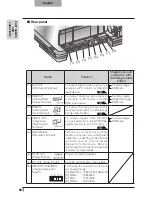
Rear panel
(1) (2)
(3) (4)
(5)
(7) (8)
(6)
Name
Function
Images you can
change to with
the Image select
button
(1) DVI OUT
(DVI Output Terminal)
To output digital video signal to a
projector, a PC monitor, or other DVI
input device.
P.98
Camera image
SD Mode
(2) RGB OUT
(Analog RGB
Output Terminal)
To output analog video signal to
a projector, a PC monitor, or other
RGB input device.
P.99
Camera image
[RGB IN] Image
SD Mode
(3) RGB IN
(Analog RGB
Input Terminal)
To output the image input to this
terminal when [PC] is selected by
Image select button.
P.99
(4) VIDEO OUT
(Composite
Video Output
Terminal)
To output images from the RCA
pin-jack terminal to the NTSC/PAL-
system monitor (e.g., TV monitor).
P.99
Camera image
SD Mode
(5) RECORDER
(Recorder Terminal)
Terminal to connect the optional
desktop recorder via a dedicated
cable. By connecting to the desktop
recorder, you can record camera
images from this device. Refer to
the manual for the optional desktop
recorder for more details.
(6) DC IN 12V
(Power Socket)
Plug-in for the AC adapter.
(7) DC OUT (Power Outlet)
Connect optional items and output.
(8) RESOLUTION/VIDEO
(Change Resolution
Switch)
A B C D
To change the resolution of the out-
put analog image.
[A] SXGA/720p : 1280x1024/1280x720
[B] WXGA
: 1280x800
[C] XGA
: 1024x768
[D] VIDEO
: NTSC/PAL
Summary of Contents for Teacher's Choice P10
Page 2: ......


