12
CHAIN LOOPER THREAD TAKE UP ROTARY CAM
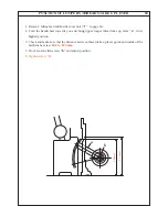
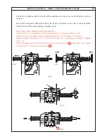
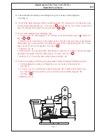
1. Timing adjustment for chain looper thread take up rotary Cam
"c"
:
When the small hole
"d"
on
"c"
adjoins at the surface of chain looper thread guide plate
"a"
, the needle
"L2"
in its downward movement must be positioned as shown in Fig.1.
2. Setting for the timing adjustment:
Loosen the screws
"e"
, then turn
"c"
, either in the direction of
"F"
or
"R"
depend on the
requirement, until
"c"
is set as shown in Fig.2. Tighten the screws
"e"
.
Screw driver can insert out of left side opening between left side
"c"
and
"a"
near by set
screws on the setting stud of
"c"
.
3. When chain looper stitch formation shows either too tight (Fig.3) or too loose (Fig.4), this
can be corrected with the following manner:
In case of too tight (stitch formation), loosen the screws
"e"
and turn (adjust)
"c"
,
slightly (may be about for a small hole) in the
"F"
direction. At the contrary, in case of
too loose, turn (adjust)
"c"
, slightly (may be about for a small hole) in the
"R"
direction.After correcting properly, tighten the screws
"e"
.
4. Beside above adjustment, if chain looper thread holder
"b"
placed upper, stitch formation
becomes tight and placed lower, stitch formation becomes loose.
In connection with above adjustment (correction), if
"a"
adjusted toward upper position,
Chain looper thread stitch formation becomes loose and if adjusted to the lower, Chain
looper thread stitch formation becomes tight. It is required to make sure that
"c"
takes up
chain looper thread properly when
"a"
adjusted its set position at the highest of adjustable
long hole of
"a"
.
Fig.2
Fig.1
R
F
2mm
L2
c
d
e
c
a
b
Fig.4
Fig.3
=
=
Summary of Contents for 745 -
Page 1: ...745 845 SERVICE MANUAL 2 2 5 5 1 3 5 NA 6 0 B 1 2 1 T P T P...
Page 18: ...a HEIGHT AND ALIGNMENT OF CLOTH PRESSER BAR 4a 5 b c 4 7mm...
Page 24: ...TIMING OF LOWER LOOPER 8a A B C D b a 5 2mm R1 Fig 1 Fig 2 Fig 3...
Page 51: ...ANNEX SETTING POSITIONS OF SL DF DIALS b c f d g e 2 1 C B A...
Page 61: ...M E M O...


