23
Model 8300
8
1
2
3
4
5
6
7
9
10
11
12
13
14
15
16
17
18
19
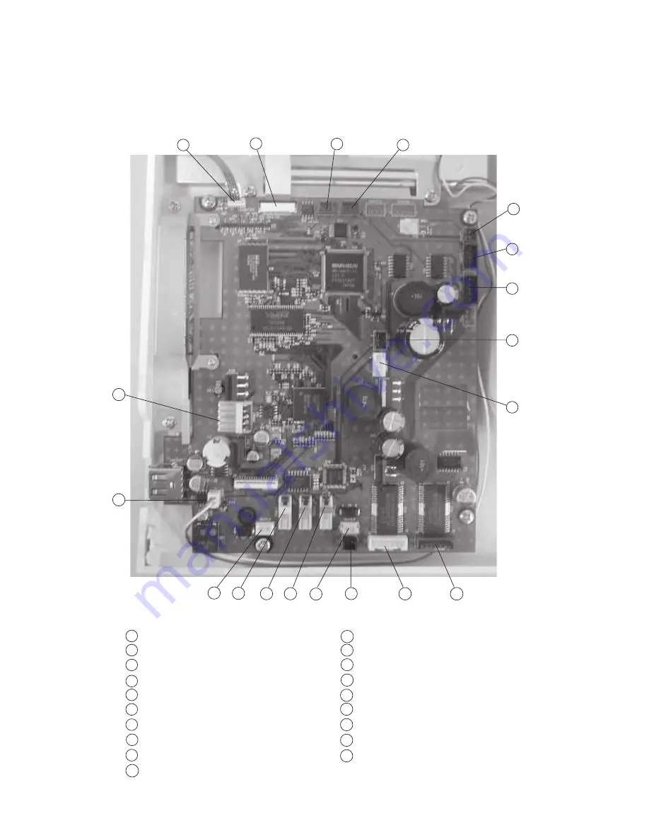
Connector Connection Diagram
Please see the following connector connection diagram for the printed circuit board A.
Touch panel
LCD Harness
Presser foot lifter sensor (Red)
Thread detection sensor ( Red )
Bobbin winder sensor (Black)
Upper shaft sensor (Black)
Printed circuit board F (Black)
Remaining bobbin thread sensor (Blue)
Switching power supply ( White )
X- Motor ( Blue )
Y- Motor (White)
Thread cutter switch (Black)
Thread cutter solenoid (Red)
Solenoid for thread tension (Red)
Remaining bobbin thread solenoid (Blue)
Lamp (White)
Needle thread solenoid (White)
Inverter (White)
DC Motor (White)
8
1
2
3
4
5
6
7
9
10
11
12
13
14
15
16
17
18
19
Summary of Contents for 8300 - LEAFLET
Page 1: ...SERVICE MANUAL PARTS LIST MODEL 8300 ...
Page 47: ...PARTS LIST 45 MODEL 8300 1 2 3 4 5 6 7 8 9 11 10 6 8 ...
Page 59: ...PARTS LIST 57 MODEL 8300 1 2 3 4 5 6 7 8 13 10 11 12 13 13 14 15 16 17 17 18 19 20 21 22 13 9 ...
Page 67: ...PARTS LIST 65 MODEL 8300 1 2 3 4 5 6 7 8 8 9 8 10 11 12 13 14 15 16 17 18 19 20 21 ...
Page 69: ...PARTS LIST 67 MODEL 8300 1 2 3 4 5 6 7 8 9 10 11 12 13 14 15 17 18 16 ...