background image


6

1. Item Checklist 

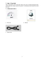
Take out the system unit from the carton. Remove the unit by carefully clutching the foam 
inserts and remove slowly to protect the system. The following contents should be found in 
the carton: 

1.1 Standard Items 


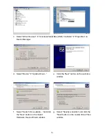
a. Driver CD 

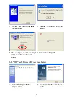
  b. Manual 


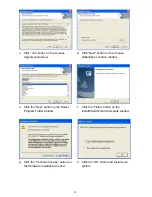
c. Power 

Cable 


Summary of Contents for POS 66X Series

Page 1: ...POS 66X Series User Manual Point of Sale Hardware System P N 48201132 2006 June V1 1...

Page 2: ...or incidental or consequential damages in connection with the furnishing performance or use of this material This document contains proprietary information that is protected by copyright All rights ar...

Page 3: ...should never be placed near or over a radiator or heat register or in a built in installation unless proper ventilation is provided 7 This product should be operated from the type of power indicated...

Page 4: ...its working life Instead the device should be taken to the waste collection centers for activation of the treatment collection recycling and disposal procedure To prevent possible harm to the environm...

Page 5: ...reen Driver Installation 16 3 8 POSTouch Screen Driver Installation 18 4 Peripherals Installation 21 4 1 Magnetic Card Reader Installation 21 4 2 Cash Drawer Installation 22 4 3 Customer Display Insta...

Page 6: ...system unit from the carton Remove the unit by carefully clutching the foam inserts and remove slowly to protect the system The following contents should be found in the carton 1 1 Standard Items a D...

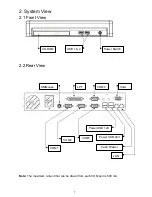
Page 7: ...ew 2 1 Front View 2 2 Rear View Note The maximum current that can be drawn from each COM port is 500 mA LPT COM4 VGA COM3 KB Mouse LAN Cash Drawer Power USB 24V Power USB 12V COM2 COM1 CD ROM USB 1 2...

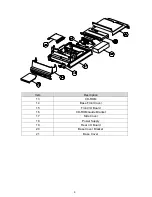
Page 8: ...awing Item Description 1 Front Bezel 2 Touch Panel 3 LCD Panel 4 LCD Chassis 5 Main Board 6 Inverter 7 MSR Function Board 8 Touch Bridge Board 9 Thermal Module 10 LCD Cover Assembly 11 MSR Dummy Door...

Page 9: ...9 Item Description 13 CD ROM 14 Base Front Cover 15 Front I O Board 16 CD ROM Guide Bracket 17 Side Cover 18 Power Supply 19 Rear I O Board 20 Base Cover Bracket 21 Base Cover...

Page 10: ...Driver CD Common Intel USB20 USB 2 0 Driver CD Common Elo_Touch ELO Touch Screen Driver CD Common POS_Touch POSTouch Screen Driver The following procedures are for Windows 2000 XP other platforms are...

Page 11: ...your system 3 3 VGA Driver Installation a Double click win2k_xp147 on the My Computer window b Click the Next button on the Welcome window c Click the Next button on the Welcome window d Click the Ye...

Page 12: ...em 3 4 Audio Driver Installation a Double click wdm_93631 on the My Computer window b Click the Next button on the Welcome window c Click the Continue Anyway button on the Hardware Installation window...

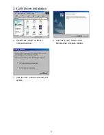
Page 13: ...13 3 5 LAN Driver Installation a Double click Setup on the My Computer window b Click the Finish button on the Maintenance Complete window c Click the OK button and restart your system...

Page 14: ...developer site Windows 98 Retail Developers and OEMs should contact Orange Ware For end users if your device does not ship with Windows 98 drivers contact your device or system manufacturer If USB 2 0...

Page 15: ...ice Manager d Select Device Update Driver e Click the Next button on the welcome window f Select Search for a suitable and click the Next button on the Install Hardware Device Drivers window g Select...

Page 16: ...to next page i Click the Next button on Driver Files Search Results window j Click the Finish button to complete this process k Finished 3 7 ELO Touch Screen Driver Installation a Click sw500930 on th...

Page 17: ...hen click the Next button on the Welcome window e Click the Yes button on the License Agreement window f Click the Next button on the on the Select the COM ports window g Select COM5 and click the Nex...

Page 18: ...utton and restart your system k After the computer restarted click Align on the Elo Touchscreen Properties window l Calibrate three red points 3 8 POSTouch Screen Driver Installation a Double click Se...

Page 19: ...Choose Destination Location window e Click the Next button on the Select Program Folder window f Click the Finish button on the InstallShield Wizard Complete window g Click the Continue Anyway button...

Page 20: ...Scan RS232 Touch Device j Automatically scan serial port for touch k Select Programs TouchUtility Touch Utility l Click Scale Offset on the POSTouch Utility window m Calibrate three red flash points n...

Page 21: ...n 4 1 Magnetic Card Reader Installation The MSR unit is tested and can be supplied at your request This MSR is removed during transportation and can be connected by the user There are two types of MSR...

Page 22: ...ment 4 2 2 Cash Drawer Controller Register The Cash Drawer Controller use one I O addresses to control the Cash Drawer The Cash Drawer Control Register and the Cash Drawer Status Register Register Loc...

Page 23: ...er Bit 0 Cash Drawer DOUT bit0 pin output control 1 Opening the Cash Drawer 0 Allow closing the Cash Drawer Note Please follow the Cash Drawer control signal design to control the Cash Drawer 4 2 3 Ca...

Page 24: ...h the hole b Pass the cable through the pole Place the short or long pole into the hole c Tighten the screws 2 under the pole d Connect the cable Please setup the COM port power e Connect the cable in...

Page 25: ...ting the second display a Connect the VGA cable male into the second display b Mount the second display on the rear of the system and tighten the screws 3 on the supporter All these screws are behind...

Page 26: ...Cover a Loosen the thumbscrews 2 b Slide the top cover towards the back and remove it c Remove the screws 2 d Pull the base cover bracket towards you by the handle and lift it up e Fix the base cover...

Page 27: ...eps in chapter 5 1 a Disconnect the IDE cable 1 and power cable 1 b Remove the screws 4 to replace the HDD 5 3 Replace the Power Supply a Remove the screws 2 b Disconnect the 20pin cable 1 c Remove th...

Page 28: ...ve it c The memory slots are located on the mainboard To remove the memory module use your finger to push the DIMM slot ejector clips into the down position d Remove the memory module from the slot e...

Page 29: ...the socket and lift it up 5 5 Remove the Mainboard a Remove the screws 2 b Lift the cover up and remove it c Disconnect the cables 8 2nd VGA cable 20pin cable 100pin cable IDE1 cable IDE2 cable USB3...

Page 30: ...le sign that faces to the white power connector e Remove the screws 2 f Use your hands to carefully press in the two sides to separate the LCD chassis from the base including LCD cover g Disconnec the...

Page 31: ...sconnect the cables 3 j Remove the screws 8 of the mainboard 5 6 Replace Touch Board a Disconnect the cables 2 b Remove the screws 2 5 7 Replace Inverter Board a Disconnect the cables 2 b Remove the s...

Page 32: ...768 Touch Screen Type Resistive Tilt Angle Degree 0 70 Storage HDD 1 x 3 5 Drive Bay ODD 1 x Slim CD ROM CD RW DVD ROM Drive Bay Flash Memory Compact Flash Type I II Expansion Mini PCI Socket 1 Extern...

Page 33: ...H non condensing Peripherals Input Device Magnetic Card Reader 3 Tracks RS 232 PS2 Interface Output Device Second Display 8 4 10 4 12 1 TFT LCD Customer Display VFD LCD POS662 317 x 355 x 336 mm 12 5...

Page 34: ...34 Appendix B Jumper Settings B82 Motherboard...

Page 35: ...et 3 Change the JP5 jumper setting from N C to 1 2 4 Wait 1 minute 5 Change the JP5 jumper setting back to N C 6 Close the cabinet 7 Apply AC power and continue 3 Power Mode Setting Function JP9 SHORT...

Page 36: ...EN SHORT SHORT 5 800 x 600 24 Single SHORT OPEN SHORT OPEN I O Board Tilt the terminal and remove the Jumper Cover Plate 1 screw on the bottom of the terminal to gain access to the jumpers 1 COM1 COM2...

Page 37: ...8 9 10 11 12 13 14 15 16 17 18 19 20 21 22 23 24 12V 5V RI 12V 5V DCD 12V 5V RI 12V 5V DCD PIN9 PIN1 PIN9 PIN1 Factory Default Setting 3 USB DC Power Jumper Setting JP3 JP4 SHORT JP3 SHORT JP4 SHORT...

Page 38: ...is displayed during POST the Power on Self Test Press DEL to enter SETUP 3 The main menu of the BIOS setup is displayed 4 If the supervisor password is set you must enter it here 3 When a Problem Occu...

Page 39: ...ated peripherals Power Management setup Use this menu to specify your settings for power management PnP PCI Configurations This entry appears if your system supports Plug and Play and PCI Configuratio...

Page 40: ...or user password Set Password Change set or disable the password It allows you to limit access to the system and to the setup or just to the setup Save exit setup Save CMOS value changes to CMOS and...

Reviews: