background image

en

Nano push-button

6 / 6

08.08.2017

version 1.0

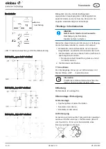
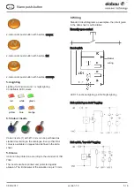
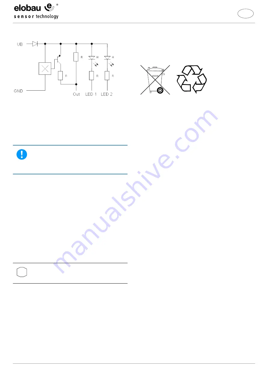
Hall switch, “high side” toggling

The output signals given in the data sheet diagram
depending on the load resistance (in the technical data,
the values are given as standard at 10kΩ).

7 Assembly / Commissioning

NOTE

Danger due to incorrect connected loads.

Damage to the nano push-button.

Observe electrical specifications.

Make these instructions available to the persons who
install, maintain and operate the nano push-button.

Ø

Ensure that the nano push-button is only installed by
trained, authorised personnel.

1. Assemble the nano push-button on a level surface

(free of mechanical torsion).

ð

Insert the nano push-button into the installation
opening and counter with the nut.

2. Connect the nano push-button.

7.1 Connection

If required, the braid outlets can be equipped with plugs
(Molex, AMP, …).

i

Information

Observe polarity of the LED connections. If the
polarity is incorrect, the LED is not lit.

8 Maintenance

The nano push-button is maintenance-free.

9 Disassembly / Disposal

9.1 Disassembly

Ø

Disconnect from voltage.

▸ Disassemble nano push-button.

ü

The nano push-button is disassembled.

9.2 Disposal

Dispose of packaging and used parts in accordance with
the relevant national regulations. Dispose of the nano
push-button separately from domestic waste, e.g. at a
collection point of a disposal company.

Summary of Contents for 145NT Series

Page 1: ...te Lebensdauer sicher und griffbereit ablegen Grundsätzlich sind die am Aufstellungsort geltenden Vorschriften Anweisungen und Sicherheitshinweise vor Inbetriebnahme sowie während des Betriebs einzuhalten 1 1 Zeichen und Symbole Handlungsschritt Fordert zum Handeln auf ü Handlungsergebnis 1 Positionsnummer Verweist auf die Positionsnummer in einer Abbildung Aufzählung i Information Weist auf effek...

Page 2: ...use betreiben Die Nanotaste nur sachgerecht und bestimmungsge mäß verwenden Bei Zuwiderhandlungen erlischt jeg liche Garantie und Herstellerverantwortung Sicherstellen dass die Sicherheitsbestimmungen der einzelnen Maschinen beachtet werden Sicherstellen dass die internationalen und nationalen Bestimmungen beachtet werden Tasten dürfen nicht in ferritischen Materialien mon tiert werden Vernüftiger...

Page 3: ...rer bestimmungsgemäßen Verwendung Konstruktiv konnte der vernünftigerweise vorhersehbare Fehlgebrauch vermieden werden ohne die bestimmungsgemäße Funktionalität einzuschränken 2 5 Veränderungen und Umbau Jegliche eigenmächtige Veränderung und Umbau sind ausdrücklich verboten 3 Transport und Lagerung Die Nanotaste während der Lagerung vor Wärme Feuchtigkeit Chemikalien und Stößen schützen 4 Technis...

Page 4: ...Kennwerte Schaltspannung Max 30 V AC DC Schaltstrom Max 0 3 A DC Schaltleistung Max 3 W VA Betriebsspannung LED Typisch 5 V 12 V 24V abhängig vom Vorwiderstand Betriebsspannung Hall Switch 5 V 10 Stromaufnahme Hall Switch max 2 5 mA MTTF Reedschalter 2111 Jahre ohne LED 436 Jahre mit LED MTTF Hall Switch 296 24 Jahre ohne LEDs 217 30 Jahre mit LEDs EMV Beständigkeit Reedschalter gemäß ISO 7637 3 2...

Page 5: ...s für Farbeinleger 2 Komponenten Drücker mit Haptik konvex 2 Komponenten Drücker mit Haptik flach 2 Komponenten Drücker mit Haptik konkav 5 4 Beleuchtung Beleuchtung für Funktions und oder Nachtbeleuchtung Ansteuerbare LED Farben rot weiß grün gelb blau orange 5 5 Farbeinleger 1 Farbeinleger 1 mit Ø 12 mm sind gemäß Katalog als Standard beziehbar Jede andere RAL Farbe ist nach Rücksprache möglich ...

Page 6: ...Ø Sicherstellen dass die Nanotaste nur von speziell ausgebildetem autorisiertem Personal montiert wird 1 Die Nanotaste auf einer ebenen Fläche mechanisch spannungsfrei montieren ð Nanotaste in die Einbauöffnung stecken und mit der Mutter kontern 2 Die Nanotaste anschließen 7 1 Anschluss Die Litzenabgänge können je nach Erfordernissen mit Stecker Molex AMP bestückt werden i Information Polarität de...

Page 7: ...safe accessible place throughout the useful life The regulations instructions and safety information valid at the place of installation are always to be observed before commissioning and during operation 1 1 Icons and Symbols Operating step Requires an action ü Result of action 1 Item number Refers to the item number in a diagram List i Information Indicates the most effective or most practical us...

Page 8: ...ano push button correctly and for its in tended purpose In the event of infringement all war ranty claims and responsibility of the manufacturer are excluded Ensure that the safety regulations of the individual machines are observed Ensure that the national and international regulations are observed Keys must not be installed in ferritic materials Reasonably predictable incorrect use Improper use ...

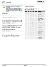
Page 9: ...tended use 2 5 Modifications and Conversions All unauthorised modifications and conversions are strictly prohibited 3 Transport and Storage Protect the nano push button against heat humidity chemicals and shocks during storage 4 Technical Specifications 4 1 Designation type key Article No nano push button 1 3 4 5 6 7 8 9 10 Note 145 NT nano push button G Threaded housing and reed switch H Threaded...

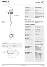
Page 10: ... Hall switch 296 24 years without LEDs 217 30 years with LEDs EMC resistance reed switch pursuant to ISO 7637 3 2007 ISO 7637 3 200 ISO 10605 2008 ISO 16750 2 2012 EMC resistance Hall switch pursuant to DIN EN 14982 2009 DIN EN 55025 2009 ISO 11452 2 2004 ISO 11452 4 2005 ISO 11452 5 2002 ISO 11452 8 2015 ISO 7637 3 2007 ISO 10605 2008 4 7 Other information Working temperature range 40 C 85 C Stor...

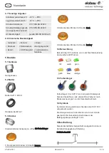
Page 11: ...rchased as standard according to the catalogue Every other RAL colour is available on request and defined in the data sheet 5 6 Icons Icons can be printed on according to the standard of ISO 7000 The inserts are back printed and protected against abrasion The lit diameter of the actuation cap is 10 mm 6 Wiring Standard circuit diagrams as examples the circuit given in the data sheet is authoritati...

Page 12: ... nano push button on a level surface free of mechanical torsion ð Insert the nano push button into the installation opening and counter with the nut 2 Connect the nano push button 7 1 Connection If required the braid outlets can be equipped with plugs Molex AMP i Information Observe polarity of the LED connections If the polarity is incorrect the LED is not lit 8 Maintenance The nano push button i...

Reviews: