Art.-Nr./Art. No./Réf./N° art/N° art.: 9010005B01M
Version/Version/Version/Versione/Versión: 1.0
Datum/Date/Date/Data/Fecha: 15.02.2016 4/21
153...
4
Safety instructions
5
Warning against misuse
6
Exclusion of liability
No liability shall be accepted for any damage or operational faults caused by
a failure to observe these operating instructions. All further liability of the
manufacturer is excluded in the case of damage caused by the use of
replacement and accessory parts that have not been authorized by the
manufacturer.
No unauthorized repairs, conversions or modifications are permitted for
reasons of safety and the manufacturer shall not be liable for any damage
resulting therefrom.
7
Function
A coded magnetic safety sensor with a non-contact activation through a coded
actuator.
(Type 4; low coding level according to EN ISO 14119)
An elobau safety control unit or similar safety processing unit / safety controller
analyses the switching state of the safety sensor.
The safety sensors are suitable for the following elobau safety control units:
8
Technical specifications
See Technical specifications starting on page 13.
9
Installation
- Safety sensor and actuator
do not use as end stops
do not install in strong magnetic fields
do not expose to any strong shocks or vibrations
keep away from iron filings
- The safety sensor and the accompanying actuators may only be mounted in
a voltage-free state.
- Ensure that all safety sensor and actuator markings are congruently
opposed to one another.
- The installation position is arbitrary. The safety sensor and actuator must
however be mounted in parallel, facing each other.
- Please note the specified installation tolerances and the approved control
options.
- Since the safety sensor is a non-embeddable proximity switch (in accor-
dance with EN 60947-5-2), the safety sensor and the actuator should be
mounted on non-ferromagnetic material. A free zone of 25 mm is required in
the event that this cannot be avoided.
- Do not attach the safety sensor and actuator to ferromagnetic material. If
necessary, use 20 mm of non-ferromagnetic material to attach the safety
sensor and actuator. The above-mentioned free zone still applies to the
safety sensor and actuator.
- Ensure that the safety sensors are only mounted and put into
operation by specially-trained and authorised personnel.
- Only install and put the device into operation once you have
read and understood the operating instructions and are familiar
with the applicable regulations on occupational safety and
accident prevention.
- The safety sensor may only be activated by a correctly mounted
actuator on the safety device. Actuation by means of a spare
actuator that is not mounted to the safety device is prohibited.
- The safety sensors may only be operated in a perfect
functioning condition.
- Ensure that the safety sensors are exclusively used to protect
against risks.
- Ensure that all of the valid safety regulations for the respective
machine are complied with.
- Ensure that all of the valid laws and directives are complied with.
- Connecting safety sensors in series can, under certain
circumstances, reduce their performance level according to
EN ISO 13849-1 standards due to a lower detection of errors.
- There are no known residual risks, if all of the information
contained in these operating instructions is complied with.
- In case of incorrect or unintended use or manipulation, the use
of the safety sensors does not exclude risks to persons or
damage to machine or system components. Please also
observe the relevant information stipulated in EN ISO 14119.
- Please ensure that when using safety control units that have not
been supplied by elobau, no current or voltage peaks which are
higher than the specified electrical data of the safety sensor are
generated by these devices. Current or voltage peaks are pro-
duced, for example, by capacitive or inductive loads.
- The safety sensor is not short-circuit proof.
- An exceeding of the electrical data of the safety sensor (e.g. in
the event of incorrect wiring or short-circuits) may cause irrepa-
rable damage to the safety sensor.
- The safety sensor may only be activated in the approved control
options (see Technical specifications).
Non-compliance with this information may result in reduced ser-
vice life of the safety sensor.
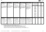
Safety sensor
Type 3
according to EN ISO 14119
Type 4
according to EN ISO 14119
153260
✓
153262
✓
153262AFA
✓
153262A01
✓
153262S
✓
153262SA01
✓
153262SAFA
✓
153V62
✓
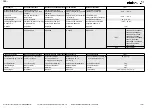
Safety sensor
Type 3
according to EN ISO 14119
Type 4
according to EN ISO 14119
153V6201
✓
153V62S
✓
153V62A0D
✓
153V62SHD
✓
153270
✓
153270AA
✓
153270A0D
✓
153270A0E
✓
153270S
✓
153270SA
✓
153270SA0D
✓
153270AW01
✓
Safety sensor
Suitable evaluation unit
153260
471M41H31
153262
153262AFA
153262A01
153262S
153262SA01
153262SAFA
153V62
46311.B.
47011.B1
47.EFR..
485EP..
153V6201
153V62S
153V62A0D
153V62SHD
153270
47.EFR..
485EP..
46212.E1.
462121H.
46312.B1
47012.B1
470121H1.
470221E1U
153270AA
153270A0D
153270A0E
153270S
153270SA
153270SA0D
153270AW01


