Art.-Nr./Art. No./Réf./N° art/N° art.: 9010007B01M
Version/Version/Version/Versione/Versión: 1.2
Datum/Date/Date/Data/Fecha: 21.03.2017 3/15
11 Wartung
Das Schaltverhalten jedes Sicherheitskreises muss mindestens einmal pro
Jahr kontrolliert werden.
12 Störungsbeseitigung
13 Entsorgung
Verpackung und verbrauchte Teile gemäß den Bestimmungen des Landes, in
dem das Gerät installiert wird, entsorgen.
Safety control unit eloFlex 470EFR
Translation of the original operating instructions
Table of contents
In these operating instructions..............................................................3
Designated use.....................................................................................3
Warning against misuse .......................................................................3
Technical specifications........................................................................4
Electrical connection.............................................................................4
Commissioning .....................................................................................5
Troubleshooting....................................................................................5
Declaration of conformity ..............................................................................16
1
In these operating instructions
The following standard models are described:
- 470EFR2D12K_
SIL2/PLd with 2 safety outputs
- 470EFR3E12K_
SIL3/PLe with 2 safety outputs
- 470EFR3E11K_
SIL3/PLe with 1 safety output
The selected configuration can be obtained from the data sheet.
The person installing the safety control unit is to be provided with the operating
instructions.
The operating instructions and the data sheet must be kept in a legible condi-
tion and in an accessible location.
Meaning of the symbols used:
2
Designated use
The safety control unit is an integral part of the overall system or machine and
serves for performing safety-related functions.
This is done by monitoring signals by e.g. safety sensors, emergency-stop
buttons, position switches, no-contact protective equipment BWS. The
product must exclusively be applied in accordance with the descriptions
below.
3
Safety instructions
4
Warning against misuse
5
Exclusion of liability
No liability shall be accepted for damage and operational faults caused by a failure
to observe these operating instructions. All further liability of the manufacturer is
excluded in the case of damage caused by the use of replacement and accessory
parts that have not been authorised by the manufacturer.
No unauthorized repairs, conversions and changes are permitted for reasons of
safety and the manufacturer shall not be liable for damage resulting therefrom.
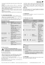
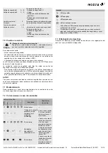
LEDs eloFlex Mini
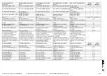
Bedeutung
Fehlerbehebung
Rea
dy
Error
I1
I2
O1
O2
Normalbetrieb
—
Karenzzeit
überschritten, nur
betroffene(r)
Eingang(e) blinkt(en)
Tür öffnen und
schließen. Wenn
Fehler bestehen
bleibt, Sensor/
Schaltgerät tauschen.
interner Fehler
Versorgungsspan-
nung neu anlegen
2
.
Wenn Fehler beste-
hen bleibt, Auswerte-
einheit tauschen
1
1
Eingang(e)
vorhanden, Start
erwartet
Rückführkreis
prüfen: Ist Startsignal
am Eingang Start 1
(Klemme 1/2)
vorhanden?
Interner Fehler
Versorgungsspan-
nung neu anlegen
2
.
Wenn Fehler beste-
hen bleibt, Auswerte-
einheit tauschen.
Legende
LED an
LED aus
LED blinkt
LED beliebiger Zustand
Anzahl der leuchtenden/blinkenden LEDs ist abhängig von der
Konfiguration der eloFlex
Beachten, dass während einem Spannungsreset keine externe
Spannung an den Sicherheitseingängen anliegt (z.B. durch Geräte
mit OSSD-Ausgängen).
1
2
GB
Warning
Failure to observe this warning may result in faults or malfunc-
tions.
Failure to observe this warning may result in personal injury
and/or damage to the machine.
- Ensure that the safety control unit is only put into operation by
specially-trained authorised personnel.
- Only install and put the device into operation once you have
read and understood the operating instructions and are familiar
with the applicable regulations on occupational safety and
accident prevention.
- Ensure that the corresponding fuses (see technical specifica-
tions) are used. Never bypass or repair fuses.
- Ensure that the safety control unit is only used to protect against
dangers.
- Ensure that all safety requirements applying for the machine in
question are observed.
- Ensure that all applicable European directives and national
laws/directives are observed.
- Ensure that the control output is only used for displaying the
operational status of the safety control unit.
- There are no known residual risks if all of the information
contained in these operating instructions is complied with.
- In case of incorrect or unintended use or manipulation, the use
of the safety control unit does not exclude risks to persons or
damage to machine or system components.
Please also observe the relevant information stipulated in the
ISO 14119 standards.
- Ensure that no current or voltage peaks which are higher than
the specified electrical data of the safety control unit are caused
by external components. Current or voltage peaks may for
example be generated through capacitive or inductive loads.
- An exceeding of the electrical data of the safety control unit (e.g.
in the event of incorrect wiring or short-circuits) may cause
irreparable damage to the unit. Non-compliance may result in
reduced service life.

