Art.-Nr./Art. No./Réf./N° art/N° art.: 9010007B01M
Version/Version/Version/Versione/Versión: 1.2
Datum/Date/Date/Data/Fecha: 21.03.2017 4/15
6
Function
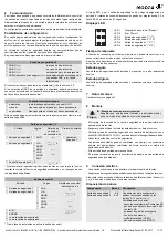
2 safety inputs, that can be connected differently, connect the safety resp. the
control outputs depending on the configurable, logical connection. In addition,
there is an input available for reading external contactors and start buttons.
The details of configuration can be obtained from the data sheet.
Configuration possibilities
On our website www.elobau.com you will find the eloFlex Configurator, which
offers a step-by-step guide to derive your required configuration. Clicking on
underlined terms and functions serves to open an explanatory window to
explain the items in more detail.
The micro-controller controlled safety control unit can be delivered with the
following configuration possibilities.
Each component can be individually adjusted.
Upon connection of a sensor, the (+) potential must be disconnected from
terminals 5 and 9.
Upon selection of OSSD at the safety input, a sensor with cross-short detection
must be used or any errors resulting from cross-shorts must be ruled out.
Maximum one external contactor input can be assigned to one safety output.
* When selecting the logic operator, ensure that the resulting function fulfils the
specified safety function and corresponds to the specified properties.
* The control output is switched on after initialization.
There is no input assignment for the selection of BTR, fault or safety output.
The switch on/switch off delay of the outputs can be chosen from 0.0 s until
99.9 s in 0.1 second steps.
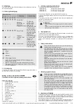
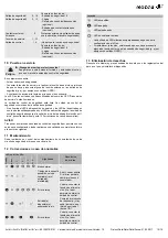
LED displays
Operating time
The operating time is the maximum time permitted on a sensor between
actuation of both sensor contacts.
With 2-hand operation, it is the maximum time permitted between actuation of
both sensors.
Safe condition
The safety outputs are opened or with high resistance.
Hazardous condition
The safety outputs are closed or with low resistance.
7
Technical specifications
See technical specifications on page 13.
8
Installation
- Installation of the safety control unit is only permitted in a voltage-free state.
- Ensure that the required fuses (see technical specifications) are used.
- Snap the safety control unit onto a mounting rail (DIN EN 60715 TH35) in the
switch cabinet. The safety control unit is attached.
- Connect the safety control unit.
The pluggable terminal blocks can be coded by means of pins, the sockets
in the device are inversely coded by means of coding tabs
- If the safety input remains free:
Ensure that the contact makers of this safety input are bridged.
9
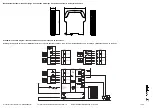
Electrical connection
- The electrical connection is only permitted in a voltage-free state.
- Make sure that the specifications described in the technical data are always
complied with.
Upon connection of a sensor, the (+) and (-) sensor supply voltage must be
used by the terminals stated in the technical data.
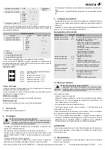
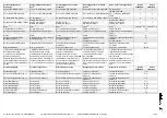
Terminal connections
Safety input 1-2
NO/NO (-/+)
e.g. protective door
NO/NC (-/+)
e.g. protective door
NC/NC (-/+)
Emergency-stop push-button
OSSD (safe semiconductor)
(+/+)
only safe sensors with PNP outputs,
e.g. light grids
External contactor/start
automatic
Automatic start/restart with HIGH level
manual
Release at rising flank
monitored
Release at falling flank
Safety output 1-2
Input
Logic *
Switch on/switch
off delay in s
External monitoring
Safety input 1
AND
t
ON
,
s
___
t
OFF
,
s
Contactor/
start 1
Safety input 2
OR
NAND
NOR
XOR
XNOR
NOT
Two-hand control 1 + 2
Control output
Input
Logic
Switch on/switch off
delay in s
Safety input 1
AND
t
ON
,
s
___
t
OFF
,
s
Safety input 2
OR
NAND
NOR
XOR
XNOR
NOT
BTR*
FAULT
as safety output 1
as safety output 2
Danger
Danger of electrocution!
Ensure that the safety control unit is only put into operation by
specially-trained authorised personnel.
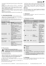
Components
Terminal/s Description
Safety input 1
5-8
Depending on configuration, the inputs at
terminals 8, 12 are (+) or (-) read-only.
Connection options:
- sensors with 2 contact maker (NO) system
- sensors with contact maker (NO)/contact
breaker (NC)
- Emergency-Stop push-button
- two-hand control
- photoelectric sensor (OSSD)
- photoelectric sensor (OSSD)
Safety input 2
9-12
Safety output 1
4, 16
Switching dependent on:
- Safety input 1-2
- Logic
- Switch on/switch off delay (optional)
- Switch on/start inputs (optional)
Safety output 2
3, 15
External contactor/
start
2
External contactor and/or start button
(automatic, manual or monitoring)
Operating voltage
1, 13
Control output
14
Not suitable for safety functions!
Switching dependent on:
- Safety input 1-2
- Logic
- Switch on/switch off delay (optional)
1
3
5
4
6
2
LED 1
Operability ("Ready")
LED 2
Fault ("Error")
LED 3
Safety input 1 ("I 1")
LED 4
Safety input 2 ("I 2")
LED 5
Safety output 1 ("O 1")
LED 6
Safety output 2 ("O 2")

