background image

elobau GmbH & Co. KG

Zeppelinstr. 44

88299 Leutkirch

Germany

Tel.:

+49 7561 970-0

Fax:

+49 7561 970-100

E-Mail:info@elobau.de

Web: www.elobau.com

Artikelnummer / Article Number / Référence / Codice articolo:  900565
Version / Version / Version / Versione:  2.0
Datum / Date / Date / Data: 04.04.2016
Seiten / Pages / Pages / Pagine:  69

Summary of Contents for 471 M41 H31

Page 1: ...ng Auswerteeinheit Translation of the original Operating instructions Control unit Traduction de la notice d utilisation d origine Unité de contrôle Traduzione delle istruzioni per l uso originali Unità di controllo D GB F I 471 M41 H31 ...

Page 2: ...900565 04 04 2016 ...

Page 3: ...2 900565 04 04 2016 ...

Page 4: ...chließer wenn nicht nötig überbrücken 13 21 30 31 32 Sensoreingang 4 S4 zwei Schließer Schließer Öffner oder Not Aus mit Querschlusserkennung wenn nicht nötig überbrücken 2 29 externer Schütz 3 und 4 wenn nicht nötig überbrücken 26 Kontrollausgang betriebsbereit 9 17 Sicherheitsausgang 1 SA1 Schließer potentialfrei 10 18 Sicherheitsausgang 2 SA2 Schließer potentialfrei 3 Kontrollausgang 1 A1 Schli...

Page 5: ...edeutung 4ab Gehäusetyp und Gehäusebreite 471 Gehäusebreite 45 mm c Ausführung M Microcontroller Ausführung d Eingänge 4 4 Eingänge e Betriebsspannung 1 24 V f Sonstiges H Kat 4 laut DIN EN ISO 13849 1 g Ausgang 3 Relaisausgang h Schaltspannung 1 30 V Betriebsspannung 24 V DC 15 Stromaufnahme 850 mA Potentialfrei Sicherheitsausgänge Schaltspannung Sicherheitsausgänge 30 V AC DC Schaltstrom Sicherh...

Page 6: ...Schaltstrom ohmsche Last 250 V AC 2 5 x 10⁵ Gebrauchsdauer in Jahren 20 Sicherung Betriebsspannung 1 A flink Sicherung Sicherheitsausgänge je 3 A Betriebstemperatur 0 C 55 C Lager und Transporttemperatur 25 C 85 C Betriebsbereitschaft ca 2 s Anzeigen LED Anschlussmöglichkeit max 4 Sensoren Vibrations und Stoßfestigkeit Schwingen 10 55 Hz 1 mm Schocken 30 g 11 ms Dauerschocken 10 g 16 ms Schutzart ...

Page 7: ...nsor 3 beide Kontakte betätigt 6 Sensor 4 beide Kontakte betätigt NOT HALT nicht betätigt 7 Sicherheitsausgang 1 durchgeschaltet 8 Sicherheitsausgang 2 durchgeschaltet 9 Sicherheitsausgang 3 durchgeschaltet 10 Sicherheitsausgang 4 durchgeschaltet Schalter Funktion 1 Verzögerung 8 s 2 Verzögerung 4 s 3 Verzögerung 2 s 4 Verzögerung 1 s 5 Sensor 4 Ö S 6 2 Hand Steuerung 7 Sensor 4 3 oder 4 Draht 8 k...

Page 8: ...iehe Technische Da ten verwendet werden Sicherungen niemals überbrücken oder reparieren Auswerteeinheit nur in unversehrtem Zustand betreiben Sicherstellen dass die Auswerteeinheit ausschließlich zum Schutz vor Ge fährdungen eingesetzt wird Sicherstellen dass alle geltenden Sicherheitsbestimmungen der entspre chenden Maschine eingehalten werden Sicherstellen dass alle geltenden europäischen Richtl...

Page 9: ...nheit ein Vor Einschalten der Sicherheitsausgänge prüft die Einheit die Schütz extern Schleife Die Schalter 7 stellen den Sensoreingang 4 auf 4 Draht Anschluss um Einheit Bestandteile 1 Sensoreingänge S1 und S2 Eingang Schütz extern 1 und 2 Sicherheitsausgänge SA1 und SA2 Kontrollausgänge A1 und A2 2 Sensoreingänge S3 und S4 Eingang Schütz extern 3 und 4 Sicherheitsausgänge SA3 und SA4 Kontrollaus...

Page 10: ...lten des Sicherheitsausgangs 4 Die Schalter stellen die Verzögerungszeit von 0 bis 15 Sekunden ein 4 Montage Auswerteeinheit im Schaltschrank auf eine Hutschiene DIN EN 60715 TH35 aufschnappen Die Auswerteeinheit ist fixiert Auswerteeinheit anschließen siehe Technische Daten Sicherstellen dass die vorgeschriebenen Sicherungen verwendet werden siehe Technische Daten Wenn eine Einheit als NOT AUS Re...

Page 11: ...egen der Betriebsspannung LED Betriebsspannung leuchtet LEDs 3 4 und 5 blinken Die Auswerteeinheit führt einen internen Selbsttest durch Nach erfolgreichem Ablauf der Prüfung Die Auswerteeinheit schaltet den Sicherheitsausgang und den Kontrollausgang durch Die LED Betriebsbereitschaft leuchtet Die Auswerteeinheit ist betriebsbereit Gefahr Lebensgefahr durch Stromschlag Sicherstellen dass die Auswe...

Page 12: ...r beiden Kontakte anlag Beide Schließer dieses Sensors öffnen Die Betriebsbereitschaft schaltet wieder ein Beide Schließer dieses Sensors schließen Die Sicherheitsausgänge schalten wieder durch Bei Verwendung eines Sensors mit Schließer Öffner an Sensoreingang 4 ist die Vorgehensweise sinngemäß gleich 6 2 Sicherheitsausgang bleibt abgeschaltet Anschlüsse an Ein und Ausgängen prüfen Betriebsspannun...

Page 13: ... Sensoren sind geöffnet Kontakte an den Sensoreingängen schließen Die LED Betriebsspannung leuchtet Die Auswerteeinheit schaltet den Ausgang durch Die Auswerteeinheit ist betriebsbereit 7 2 Entsorgung Verpackung und verbrauchte Teile gemäß den Bestimmungen des Landes in dem das Gerät installiert wird entsorgen ...

Page 14: ...900565 04 04 2016 13 D 8 Schaltbeispiele 8 1 Anschluss einer Schnittstelle 363 V98 ...

Page 15: ...14 900565 04 04 2016 D 8 2 Erweiterung der Sicherheitsausgänge ...

Page 16: ...900565 04 04 2016 15 D 8 3 2 Hand Steuerung ...

Page 17: ...16 900565 04 04 2016 D 8 4 Anschluss einer Schnittstelle 364097 ...

Page 18: ...900565 04 04 2016 17 D 8 5 NOT AUS mit Querschlusserkennung ...

Page 19: ...18 900565 04 04 2016 D 8 6 Anschluss Sensor 4 Schließer Öffner ...

Page 20: ...ker to be bridged if not needed 13 21 30 31 32 Input sensor 4 S4 two contact makers contact maker breaker or emergency off with cross short detection to be bridged if not needed 2 29 External contactor 3 and 4 to be bridged if not needed 26 Control output ready 9 17 Safety output 1 SA1 contact maker floating 10 18 Safety output 2 SA2 contact maker floating 3 Control output 1 A1 contakt maker 4 Con...

Page 21: ... mm c Version M Microcontroller version d Inputs 4 4 inputs e Operating voltage 1 24 V f Other H Category 4 according to DIN EN ISO 13849 1 g Output 3 Relay output h Switching voltage 1 30 V Operating voltage 24 V DC 15 Power consumption 850 mA Floating Safety outputs Switching voltage safety outputs 30 V AC DC Switching current safety outputs 3 A Switching power safety outputs 90 VA or 90 W Switc...

Page 22: ...puts 3 A each Operating temperature 0 C 55 C Storage and transportation temperature 25 C 85 C Operational standby Approx 2 s Indicators LED Connections Max 4 sensors Vibration and shock resistance Vibration 10 55 Hz 1 mm Shock 30 g 11 ms Continuous shock 10 g 16 ms International protection housing IP 30 International protection terminals IP 20 The switching cycles apply only to safety outputs Actu...

Page 23: ...ed Never bridge or repair fuses Only operate the control unit when it s in an undamaged condition 4 Sensor 2 both contacts actuated 5 Sensor 3 both contacts actuated 6 Sensor 4 both contacts actuated EMERGENCY STOP not actuated 7 Safety output 1 is switched through 8 Safety output 2 is switched through 9 Safety output 3 is switched through 10 Safety output 4 is switched through Switch Function 1 D...

Page 24: ...r inputs with 2 contact makers each Each sen sor input drives one control output NOTE Each control output allows controlling one SPS The safety outputs of this unit switch on when both sensor inputs of a unit are re activated Unit Components 1 Sensor inputs S1 and S2 Input external contactor 1 and 2 Safety outputs SA1 and SA2 Control outputs A1 and A2 2 Sensor inputs S3 and S4 Input external conta...

Page 25: ...8 sensors without sensor control Type 364 097 for 4 sensors with sensor control Switches 1 to 4 delay de energizing safety output 4 The switches set the delay time between 0 and 15 seconds 4 Installation Snap the control unit onto a mounting rail DIN EN 60715 TH35 in the switch cabinet The control unit is attached Connect control unit see Technical data Ensure that the prescribed fuses are used se...

Page 26: ... operating voltage applied The operating voltage LED is on LEDs 3 4 and 5 are flashing The control unit will perform an internal self test After successful completion of the test The control unit switches through the safety output and the control output The operational standby LED is lit The control unit is ready for operation Danger Danger of electrocution Ensure that the control unit is only ins...

Page 27: ...resent for more than 3 seconds on a sensor Open both contact makers of the sensor Standby mode is activated again Close both contact makers of the sensor The safety outputs will switch through again If a sensor with contact maker breaker is used on sensor input 4 the procedure is basically the same 6 2 Safety output remains switched off Check connections at inputs and outputs Operating voltage Sen...

Page 28: ...sors are open Close the contacts at the sensor inputs The operating voltage LED is on The control unit switches through the output The control unit is ready for operation 7 2 Disposal Dispose of used parts and unwanted packaging in accordance with the regula tions of the country in which the device is installed ...

Page 29: ...28 900565 04 04 2016 GB 8 Example circuits 8 1 Connection of a 363 V98 interface ...

Page 30: ...900565 04 04 2016 29 GB 8 2 Extension of the safety outputs ...

Page 31: ...30 900565 04 04 2016 GB 8 3 2 hand control ...

Page 32: ...900565 04 04 2016 31 GB 8 4 Connection of a 364097 interface ...

Page 33: ...32 900565 04 04 2016 GB 8 5 EMERGENCY OFF with cross short detection ...

Page 34: ...900565 04 04 2016 33 GB 8 6 Connection sensor 4 contact maker breaker ...

Page 35: ...34 900565 04 04 2016 GB Notizen Notes Notes Appunt ...

Page 36: ... capteur 4 S4 deux contacts de travail contact de tra vail contact de repos ou arrêt d urgence avec détection de court circuit transversal si inutile ponter 2 29 Contacteur externe 3 et 4 si inutile ponter 26 Sortie de contrôle prête à fonctionner 9 17 Sortie de sécurité 1 SA1 contact de travail sans potentiel 10 18 Sortie de sécurité 2 SA2 contact de travail sans potentiel 3 Sortie de contrôle 1 ...

Page 37: ...471 Largeur de boîtier 45 mm c Version M Version avec microcontrôleur d Entrées 4 4 entrées e Tension de service 1 24 V f Divers H Catégorie 4 suivant DIN EN ISO 13849 1 g Sortie 3 Sortie de relais h Tension de commuta tion 1 30 V Tension de service 24 V CC 15 Consommation de courant 850 mA Sans potentiel Sorties de sécurité Tension de commutation sorties de sécurité 30 V CA CC Courant de commutat...

Page 38: ...ée d utilisation en années 20 Fusible tension de service 1 A rapide Fusible sorties de sécurité 3 A chaque Température de service 0 C 55 C Température de stockage et de transport 25 C 85 C Etat de fonctionnement Env 2 s Affichages DEL Possibilité de connexion 4 capteurs max Résistance aux vibrations et aux chocs Oscillations 10 55 Hz 1 mm Chocs 30 g 11 ms Chocs continus 10 g 16 ms Classe de protec...

Page 39: ...tionnés 5 Capteur 3 les deux contacts actionnés 6 Capteur 4 les deux contacts actionnés ARRÊT D URGENCE non actionné 7 Sortie de sécurité 1 activée 8 Sortie de sécurité 2 activée 9 Sortie de sécurité 3 activée 10 Sortie de sécurité 4 activée Commuta teur Fonction 1 Temporisation 8 s 2 Temporisation 4 s 3 Temporisation 2 s 4 Temporisation 1 s 5 Capteur 4 CR CT 6 Commande à deux mains 7 Capteur 4 À ...

Page 40: ...aractéristiques techniques sont utilisés Ne jamais ponter ou réparer les fusibles Ne faire fonctionner l unité de contrôle que s il elle se trouve en parfait état S assurer que l unité de contrôle est uniquement utilisée pour la protection contre les dangers S assurer que les consignes de sécurité en vigueur de la machine concernée sont respectées S assurer que les directives européennes et les lo...

Page 41: ...n des sorties de sécurité l unité contrôle le contacteur externe de boucle Les commutateurs 7 commutent l entrée de capteur 4 sur une connexion à 4 fils Unité Composants 1 Entrées de capteur S1 et S2 Entrée contacteur externe 1 et 2 Sorties de sécurité SA1 et SA2 Sorties de contrôle A1 et A2 2 Entrées de capteur S3 et S4 Entrée contacteur externe 3 et 4 Sorties de sécurité SA3 et SA4 Sorties de co...

Page 42: ...tateurs 1 à 4 temporisent la mise en coupure de la sortie de sécurité 4 Les commutateurs règlent la temporisation entre 0 et 15 secondes 4 Montage Attacher l unité de contrôle à un profilé chapeau DIN EN 60715 TH35 dans l armoire de commande L unité de contrôle est fixée Connecter l unité de contrôle voir Caractéristiques techniques S assurer que les fusibles prévus sont utilisés voir Caractéristi...

Page 43: ...que la tension de service est branchée La DEL tension de service est allumée Les DEL 3 4 et 5 clignotent L unité de contrôle effectue un test automatique Après avoir passé le contrôle avec succès L unité de contrôle active la sortie de sécurité et la sortie de contrôle La DEL état de fonctionnement est allumée L unité de contrôle est prête à fonctionner Danger Danger de mort par électrocution S as...

Page 44: ...x contacts de travail de ce capteur L état de fonctionnement s active à nouveau Fermer les deux contacts de travail de ce capteur Les sorties de sécurité s activent à nouveau Lors de l utilisation d un capteur à contact de travail contact de repos à l entrée du capteur 4 la manière de procéder est par analogie identique 6 2 La sortie de sécurité reste déconnectée Contrôler les connexions aux entré...

Page 45: ... sont ouverts Fermer les contacts sur les entrées pour capteur La DEL tension de service est allumée L unité de contrôle active la sortie L unité de contrôle est prête à fonctionner 7 2 Élimination Éliminer les emballages et les pièces usagées conformément aux dispositions nationales du pays dans lequel l appareil est installé ...

Page 46: ...900565 04 04 2016 45 F 8 Exemples de connexions 8 1 Connexion d une interface 363 V98 ...

Page 47: ...46 900565 04 04 2016 F 8 2 Extension des sorties de sécurité ...

Page 48: ...900565 04 04 2016 47 F 8 3 Commande à deux mains ...

Page 49: ...48 900565 04 04 2016 F 8 4 Connexion d une interface 364097 ...

Page 50: ...900565 04 04 2016 49 F 8 5 ARRÊT D URGENCE avec détection de court circuit transversal ...

Page 51: ...50 900565 04 04 2016 F 8 6 Connexion du capteur 4 travail repos ...

Page 52: ...rio cavallottare 13 21 30 31 32 Ingresso sensore 4 S4 due contatti contatto NO NC o Arresto di emergenza con riconoscimento chiusure trasversali se non necessario cavallottare 2 29 Relè esterno 3 e 4 se non necessario cavallottare 26 Uscita di controllo pronta all uso 9 17 Uscita di sicurezza 1 SA1 contatto NO senza potenziale 10 18 Uscita di sicurezza 2 SA2 contatto NO senza potenziale 3 Uscita d...

Page 53: ...za dell alloggiamento 471 Larghezza dell alloggiamento 45 mm c Esecuzione M Esecuzione microcontroller d Ingressi 4 4 ingressi e Tensione di esercizio 1 24 V f Altri H Categoria 4 in conformità a DIN EN ISO 13849 1 g Uscita 3 Uscita relè h Tensione di collegamento 1 30 V Tensione di esercizio 24 V CC 15 Corrente assorbita 850 mA Senza potenziale Uscite di sicurezza Tensione di collegamento uscite ...

Page 54: ...e di commutazione pari a 3 A carico ohmico 250 V AC 2 5 x 10⁵ Durata di utilizzo in anni 20 Fusibile tensione di esercizio 1 A rapido Fusibile uscite di sicurezza 3 A ciascuna Temperatura di esercizio 0 C 55 C Temperatura di immagazzinaggio e di trasporto 25 C 85 C Idoneità operativa circa 2 s Indicatori LED Possibilità di collegamento max 4 sensori Resistenza alle vibrazione e agli urti Oscillazi...

Page 55: ... contatti inseriti 6 Sensore 4 entrami i contatti inseriti ARRESTO DI EMER GENZA non attivato 7 Uscita di sicurezza 1 collegata direttamente 8 Uscita di sicurezza 2 collegata direttamente 9 Uscita di sicurezza 3 collegata direttamente 10 Uscita di sicurezza 4 collegata direttamente Interruttore Funzione 1 Ritardo 8 s 2 Ritardo 4 s 3 Ritardo 2 s 4 Ritardo 1 s 5 Sensore 4 NC NO 6 Comando a 2 mani 7 ...

Page 56: ...i fusibili conformi all impiego vedi Specifiche tecniche Non cavallottare o riparare mai i fusibili Utilizzare l unità di controllo solamente in condizioni perfette Assicurarsi che l unità di controllo venga utilizzata esclusivamente per la pro tezione da situazioni pericolose Assicurarsi che vengano rispettate tutte le disposizioni di sicurezza della macchina Assicurarsi che vengano rispettate tu...

Page 57: ... uscite di sicurezza l unità verifica il relè circuito esterno Gli interruttori 7 commutano l ingresso sensore 4 sul collegamento a 4 conduttori Unià Componenti 1 Ingressi sensore S1 e S2 Ingresso relè esterno 1 e 2 Uscite di sicurezza SA1 e SA2 Uscite di controllo A1 e A2 2 Ingressi sensore S3 e S4 Ingresso relè esterno 3 e 4 Uscite di sicurezza SA3 e SA4 Uscite di controllo A3 e A4 Unià Utilizza...

Page 58: ...disattivazione dell uscita di sicurezza 4 Gli inter ruttori impostano il tempo di ritardo su 0 15 secondi 4 Montaggio Incastrare l unità di controllo nel quadro elettrico sulla guida DIN EN 60715 TH35 L unità di controllo è fissata Collegare l unità di controllo vedi Specifiche tecniche Assicurarsi che vengano utilizzati fusibili previsti vedi Specifiche tecniche Se un unità è usata come relè ARRE...

Page 59: ...a tensione di esercizio Il LED della tensione di esercizio si accende I LED 3 4 e 5 lampeggiano L unità di controllo esegue un test di autodiagnostica interno Se il controllo è superato L unità di controllo collega direttamente l uscita di sicurezza e l uscita di controllo Il LED dell idoneità operativa si accende L unità di controllo è pronta all uso Pericolo Pericolo di morte dovuto a scosse ele...

Page 60: ...mbi i contatti NO di questo sensore L idoneità operativa si resinserisce nuovamente Chiudere entrambi i contatti NO di questo sensore Le uscite di sicurezza si ricollegano direttamente Nel caso in cui si utilizzi un sensore con contatto NO NC in corrispondenza dell ingresso sensore 4 la procedura è fondamentalmente la stessa 6 2 L uscita di sicurezza rimange disattivata Controllare i collegamenti ...

Page 61: ...ono aperti Chiudere i contatti degli ingressi sensore Il LED della tensione di esercizio si accende L unità di controllo collega direttamente l uscita L unità di controllo è pronta all uso 7 2 Smaltimento Smaltire l imballo ed i componenti usati in conformità alla normativa del paese in cui è installato l apparecchio ...

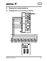
Page 62: ...900565 04 04 2016 61 I 8 Esempi di commutazione 8 1 Collegamento di un interfaccia 363 V98 ...

Page 63: ...62 900565 04 04 2016 I 8 2 Ampliamento delle uscite di sicurezza ...

Page 64: ...900565 04 04 2016 63 I 8 3 Comando a 2 mani ...

Page 65: ...64 900565 04 04 2016 I 8 4 Collegamento di un interfaccia 364097 ...

Page 66: ...900565 04 04 2016 65 I 8 5 ARRESTO DI EMERGENZA con riconoscimento chiu sure trasversali ...

Page 67: ...66 900565 04 04 2016 I 8 6 Collegamento sensore 4 contatti NO NC ...

Page 68: ... of component Logikeinheit für Sicherheitsfunktionen für Sicherheitssensoren logic unit for safety functions for safety sensors elobau Artikel Nr elobau item no 471 M41 H31 Einschlägige EG Richtlinien Relevant EC Directives Maschinenrichtlinie 2006 42 EG bis 19 04 2016 EMV Richtlinie 2004 108 EG von 20 04 2016 EMV Richtlinie 2014 30 EU Machinery Directive 2006 42 EC to 04 19 2016 EMC Directive 200...

Page 69: ...h Germany Tel 49 7561 970 0 Fax 49 7561 970 100 E Mail info elobau de Web www elobau com Artikelnummer Article Number Référence Codice articolo 900565 Version Version Version Versione 2 0 Datum Date Date Data 04 04 2016 Seiten Pages Pages Pagine 69 ...

Reviews: