background image


eloProg - Vers. 1.0 

67


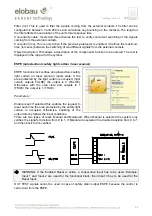
Filter (ms)

: This is used to filter the signals coming from the external contacts. The filter can be 

configured to between 3 and 250 ms and eliminates any bouncing on the contacts. The length of 
the filter affects the calculation of the unit's total response time. 


Object description

: This allows a description of the component's function to be entered. The text is 

displayed in the top part of the symbol. 


SWITCH  


SWITCH function block verifies the input status of a 
pushbutton or switch (NOT SAFETY SWITCHES). If 
the pushbutton is pressed the output is 1 (TRUE). 
Otherwise, the output is 0 (FALSE). 

Parameters 

Enabled reset

: If selected this enables the request to 

reset each time the area protected by the safety light 
curtain is occupied. Otherwise, enabling of the output 
directly follows the input conditions. 
There are two types of reset: Manual and Monitored. 
When Manual is selected the system only verifies the 
signal's transition from 0 to 1. If Monitored is selected 
the double transition from 0 to 1 and then back to 0 is 
verified

.  


Î


WARNING: If the Enabled Reset is active, a consecutive Input has to be used. Example: 
Input 1 is used for the functional block, then Input 2 has to be used for the Reset Input. 


Output test

: This is used to select which test output signals are to be sent to the emergency stop 

(mushroom pushbutton). This additional test makes it possible to detect and manage any short-
circuits between the lines. There is a choice of 4 possible test output signals, Test Output 1 ÷ Test 
Output 4.  
 

Test at start-up

: If selected this enables the test at start-up of the safety light curtain. This test is 

performed by occupying and then clearing the area protected by the safety light curtain to run a 
complete function test and enable the output. This test is only requested at machine start-up (when 
the unit is switched on). 


Summary of Contents for eloProg

Page 1: ...og Configurable safety system Manual Product description Doc No 350HB002en Last updated 05 20111 Vers 1 0 C C o o p p y y o o f f t t h h e e o o r r i i g g i i n n a a l l i i n n s s t t r r u u c...

Page 2: ...INPUTS 20 MASTER ENABLE 20 NODE SEL 20 RESTART_FBK 21 OUTPUTS 22 OUT STATUS 22 OUT TEST 22 OSSD 485EPB 485EPE08A02 485EPA02 485EPA04 22 SAFETY RELAYS 485EPR02 485EPR04 23 Characteristics of the outpu...

Page 3: ...OR I O status in real time graphic 51 Password protection 52 Level 1 password 52 Level 2 password 52 Password Change 52 TESTING the system 53 OBJECT FUNCTION BLOCKS 54 OUTPUT OBJECTS 54 OSSD safety ou...

Page 4: ...MONOSTABLE 74 PASSING MAKE CONTACT 75 DELAY 76 MUTING OPERATORS max number 4 77 Concurrent MUTING 77 MUTING L 78 Sequential MUTING 79 MUTING T 80 SPECIAL APPLICATIONS 81 Output delay with manual 81 A...

Page 5: ...ce with the applicable standards However the definitive SIL and PL of the application will depend on the number of safety components their parameters and the connections that are made as per the risk...

Page 6: ...nt requirements and tests ISO 13489 1 Safety of machinery Safety related parts of control systems General principles for design EN 61496 1 Safety of machinery Electro sensitive protective equipment Pa...

Page 7: ...l managed by a single flexible and expandable device The system must consist of just one Master 485EPB and a number of electronic expansions that can range from 0 to a maximum of 7 not more than 4 of...

Page 8: ...d separately as accessories The expansion units are supplied with Multilingual Installation sheet Rear panel connector 350EPT t fitting not present in the 485EPR02 and 485EPR04 which are connected via...

Page 9: ...P a unit use n lift the uni 1 IN rail as fo mber of t fitt ctors thus op first e rail arran Press the u a screwdr it upwards Fig ollows tings as th obtained t nging the unit gently river to pu and pu...

Page 10: ...al connections The modules are provided with terminal blocks for the electrical connections Each unit can have 8 16 or 24 terminals Each module also has a rear panel plug in connector for communicatio...

Page 11: ...31 2 8 OUT_STATUS1 Output Programmable digital output PNP active high 9 OSSD2_A Output safety output 2 PNP active high 10 OSSD2_B Output PNP active high 11 RESTART_FBK2 Input Feedback Restart 2 Input...

Page 12: ...ut The basic module 485EPB includes a USB 2 0 connector for connection to a Personal Computer where the configuration software resides The USB cable 350EPU 3m is available as an accessory Figure 2 USB...

Page 13: ...h odules with nnector y nfiguration en use it t odules to be tical to the o the config D IN THE B it with a ne to do is ins which wil minimized abled via SW eloProg mory stick emory calle led in the b...

Page 14: ...lation see the NODE SEL section Each time memory stick is used carefully check that the chosen configuration is the one that was planned for that particular system Try again a fully functional test of...

Page 15: ...61131 2 24 INPUT8 Input Digital input 8 Input according to EN 61131 2 Table 3 485EPE16 TERMINAL SIGNAL TYPE DESCRIPTION OPERATION 1 24VDC 24VDC power supply 2 NODE_SEL1 Input Node selection Input type...

Page 16: ...YPE DESCRIPTION OPERATION 1 24VDC 24VDC power supply 2 NODE_SEL1 Input Node selection Input type B according to EN 61131 2 3 NODE_SEL2 Input Input type B according to EN 61131 2 4 GND 0VDC power suppl...

Page 17: ...1131 2 12 OUT_STATUS2 Output Condition of outputs 2A 2B PNP active high 13 24VDC 24VDC power supply OSSD1 2 power supply 14 n c 15 GND 0VDC power supply 16 n c Table 7 485EPR04 TERMINAL SIGNAL TYPE DE...

Page 18: ...stem is able to detect the faults that occur in each own module Anyway to have the system perfect perform the following checks at start up and at least every one year 1 Operate a complete system TEST...

Page 19: ...l connections between the eloProg modules and with the external sensors Designing the diagram Validation sw OK NO YES Downloading the diagram to master module Configuration control on master module OK...

Page 20: ...og simply lower these inputs to logic level 0 0VDC NODE SEL The NODE_SEL1 and NODE_SEL2 inputs on the SLAVE units are used to attribute a physical address to the slave units with the connections shown...

Page 21: ...RT_FBK corresponding input The RESTART command must be installed outside the danger area in a position where the danger area and the entire concerned work area are clearly visible It must not be possi...

Page 22: ...0 75V Uv where Uv is 24V 20 In the OFF condition 0V 2V r m s The maximum load of 400mA 24V corresponds to a minimum resistive load of 60 The maximum capacitive load is 0 82 F The maximum inductive loa...

Page 23: ...oltage 10 VDC Minimum switchable current 20 mA Maximum switchable voltage DC 250VDC Maximum switchable voltage AC 400VAC Maximum switchable current 6A Response time 12ms Mechanical life of contacts 20...

Page 24: ...24 eloProg Vers 1 0 Wiring example 485EPR02 485EPB Figure 7 Switching operation timing diagram Figure 8...

Page 25: ...tive high EN 61131 2 OSSD 485EPB 485EPE08A02 485EPA02 485EPA04 PNP active high 400mA 24VDC max Digital OUTPUTS PNP active high 100mA 24VDC max Response time 485EPB 10 ms TInput_filter 485EPB 1 Slave 1...

Page 26: ...tion with RESTART button Test OUTPUT No description 4 to check for short circuits overloads Digital OUTPUTS No description 2 programmable PNP active high OSSD No description 2 pairs solid state safety...

Page 27: ...20 Dissipated power 3W max Digital OUTPUTS No description 2 4 programmable PNP active high OSSD No description 2 4 Solid state safety outputs PNP active high 400mA 24VDC max Connection to 485EPB via...

Page 28: ...28 eloProg Vers 1 0 MECHANICAL DIMENSIONS Figure 9 114 5 mm 108 mm 22 5 mm 99 mm...

Page 29: ...ncorrect connection flashes Table 23 Dynamic Screen Figure 10 Table 22 Opening Screen MEANING LED RUN IN FAIL EXT FAIL COM ENA IN1 8 OSDD1 2 CLEAR1 2 STATUS1 2 GREEN RED RED ORANGE BLUE YELLOW RED GRE...

Page 30: ...GREEN YELLOW YELLOW NORMAL OPERATION OFF if the unit is waiting for the first communication from the MASTER OFF OFF INPUT condition Shows the NODE_SEL1 2 signal table RED with output OFF GREEN with o...

Page 31: ...ORANGE YELLOW NORMAL OPERATION OFF if the unit is waiting for the first communication from the MASTER OFF OFF Shows the NODE_SEL1 2 signal table INPUT condition FLASHES if no INPUT or OUTPUT requested...

Page 32: ...ORANGE YELLOW NORMAL OPERATION OFF if the unit is waiting for the first communication from the MASTER OFF OFF Shows the NODE_SEL1 2 signal table INPUT condition FLASHES if no INPUT or OUTPUT requeste...

Page 33: ...EAR1 2 STATUS1 2 GREEN RED RED ORANGE RED GREEN YELLOW YELLOW NORMAL OPERATION OFF if the unit is waiting for the first communication from the MASTER OFF op OK OFF op OK Shows the NODE_SEL1 2 signal t...

Page 34: ...EAR1 4 STATUS1 4 GREEN RED RED ORANGE RED GREEN YELLOW YELLOW NORMAL OPERATION OFF if the unit is waiting for the first communication from the MASTER OFF op OK OFF op OK Shows the NODE_SEL1 2 signal t...

Page 35: ...NORMAL OPERATION RED with output OFF GREEN with output ON Table 35 485EPR02 Dynamic screen MEANING LED OSSD1 OSSD2 RED GREEN RED GREEN Power on initial TEST Red Red Table 36 485EPR04 Opening screen ME...

Page 36: ...rsists replace the module OSSD output error OFF 4 flashes OFF OFF OFF OFF 4 flashes only the LED corresponding to the output in FAIL mode OFF OFF Check the OSSD1 2 connections If the problem persists...

Page 37: ...u for FW upgrade OSSD output error OFF 4 flashes OFF OFF 4 flashes only the LED corresponding to the output in FAIL mode OFF OFF Check OSSD1 2 connections If the problem persists replace the module Er...

Page 38: ...5 flashes 5 flashes 5 flashes Firmware version not compatible with 485EPB return to elobau for FW upgrade Error in communication with master OFF 5 flashes OFF OFF OFF OFF OFF Restart the system If th...

Page 39: ...s 5 flashes 5 flashes 5 flashes Firmware version not compatible with 485EPB return to elobau for FW upgrade Error in communication with master OFF 5 flashes OFF OFF OFF OFF OFF Restart the system If t...

Page 40: ...FW upgrade OSSD output error OFF 4 flashes OFF 4 flashes only the LED corresponding to the output in FAIL mode OFF OFF Check OSSD1 2 connections If the problem persists replace the module Error in com...

Page 41: ...onents as described below Installing the software PC HARDWARE requirements RAM 256 MB adequate to run Windows XP SP3 Framework 3 5 Hard disk 100Mbyte of free space USB connector 1 1 or 2 0 CD ROM driv...

Page 42: ...gu unch the pro pening scre are ready to ration softw ogram doub een shown b create you ware has be ble click on below is dis r project een correctl this icon splayed Figure 23 y installed i eloProg i...

Page 43: ...USER PARAMETERS name company etc 4 SAVE THE ACTUAL PROJECT 5 LOAD AN EXISTING PROJECT 6 PRINT THE PROJECT SCHEMATIC 7 PRINT THE PROJECT REPORT 8 VALIDATE THE PROJECT 9 CONNECT TO eloProg 10 SEND PROJE...

Page 44: ...yed Figure 25 Next the configuration software displays a window showing only the 485EPB You may add the various units needed to create your system using the pull down menus at the top of the screen se...

Page 45: ...tem com dow is show meters parameters fication req from eloPro sly created mposition o mposition is wed again s is obtaine uest appea og General of the vario s obtained Figure 26 ed with the ars Figur...

Page 46: ...hese blocks are divided into 3 different types inputs outputs comments 2 OPERATOR TOOL WINDOW This contains the various function blocks for connecting the objects in point 1 these blocks are divided i...

Page 47: ...is enabled where you must fill in the fields as required When you need to set a specific numerical value with a slide ex filter use the left and right arrows on your keyboard or click the sides of the...

Page 48: ...co m 1 to 4 a e ect it you e ure the sign stage AVE on the must be ver a sequentia so listed in t ul we will pr ht gefunde cted to two ontacts of th are activated enable the block acti Figure 30 or a...

Page 49: ...lized usi level 1 with proper PC via USB e password he eloProg n from a PC 5EPB will stick Passw ble after the file proj ntification up to 5 co nt event ng the icon rties of each B cable use Enter the...

Page 50: ...u ical address em C from 485 with the sen is not com 485EPB ind s in real tim or use the ic appear in when the o w as active o puts tics tion of the e pop up wind ule s of each m 5EPB use t nt project...

Page 51: ...el 1 The color of the connecting line changes in the diagnostic view in real time RED Off GREEN On DASHED ORANGE External failure e g sensor not correct actuated DASHED RED Waiting for restart Enable...

Page 52: ...d c he project to PC eloPr LOADED th f these pass password is ange use ic allowing the ds max 8 c nnect to res ent the new word in orde st have a Le G file comp perator must can enter a re not enab on...

Page 53: ...nd the output of the E GATE block is set to high logic level in this mode the safety outputs OSSD1 2 are active and the power supply to the relative terminals is 24VDC t2 When the E GATE is physically...

Page 54: ...quest to reset is activated each time the input signal falls Otherwise enabling of the output directly follows the input conditions There are two types of reset Manual and Monitored When Manual is sel...

Page 55: ...If selected this enables the request to reset each time the emergency stop is activated Otherwise enabling of the output directly follows the input conditions There are two types of reset Manual and M...

Page 56: ...ching of the signals coming from the emergency stop Concurrent ms This is only active if the previous parameter is enabled It defines the maximum time in msecs between the switching of two different s...

Page 57: ...run a complete function test and enable the output This test is only requested at machine start up when the unit is switched on Filter ms This is used to filter the signals coming from the external co...

Page 58: ...nitored is selected the double transition from 0 to 1 and then back to 0 is verified WARNING If the Enabled Reset is active a consecutive Input has to be used Example Input 1 and Input 2 are used for...

Page 59: ...n block verifies an optoelectronic safety light curtain or laser scanner inputs state If the area protected by the light curtain is occupied light curtain outputs FALSE the output is 0 FALSE Otherwise...

Page 60: ...of two different signals from the safety light curtain Object description This allows a description of the component s function to be entered The text is displayed in the top part of the symbol FOOTS...

Page 61: ...run a complete function test and enable the output This test is only requested at machine start up when the unit is switched on Filter ms This is used to filter the signals coming from the external co...

Page 62: ...ngth of the filter affects the calculation of the unit s total response time Object description This allows a description of the component s function to be entered The text is displayed in the top par...

Page 63: ...Output 4 Test at start up If selected this enables the test at start up of the external component This test is performed by opening the mobile guard or safety gate to run a complete function test and...

Page 64: ...circuits between the lines There is a choice of 4 possible test output signals Test Output 1 Test Output 4 Test at start up If selected this enables the test at start up of the external component This...

Page 65: ...en Input 2 has to be used for the Reset Input Output test This is used to select which test output signals are to be sent to the sensor This additional test makes it possible to detect and manage any...

Page 66: ...and Input 2 are used for the functional block then Input 3 has to be used for the Reset Input Each output OUT TEST can be connected to only one input S MAT the parallel connection of 2 inputs is not a...

Page 67: ...here are two types of reset Manual and Monitored When Manual is selected the system only verifies the signal s transition from 0 to 1 If Monitored is selected the double transition from 0 to 1 and the...

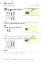
Page 68: ...a description to be entered and placed in any point of the diagram OPERATOR FUNCTION BLOCKS All the input of these operators could be inverted logical NOT It could be done clicking with the right mou...

Page 69: ...Parameters Number of inputs this is used to set between 2 and 8 inputs NOT Logical NOT inverts the logical status of the input In Out 0 1 1 0 OR Logical OR returns an output of 1 TRUE if at least one...

Page 70: ...FALSE if the input s number at 1 TRUE is even or the inputs are all 0 FALSE In1 In2 Inx Out 0 0 0 0 1 0 0 1 0 1 0 1 1 1 0 0 0 0 1 1 1 0 1 0 0 1 1 0 1 1 1 1 Parameters Number of inputs this is used to...

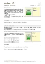
Page 71: ...n 2 and 4 inputs MEMORY OPERATORS MEMORY operators can be used if you decide to save any data TRUE or FALSE from other project components Status changes are performed according to the truth tables sho...

Page 72: ...truth table Clear Restart In Q 1 X X 0 X X 0 0 0 L 1 Keep memory 0 Rising edge 1 1 0 Falling edge 1 Keep memory Parameters Clear enable If selected enables the saving process to be reset USER RESTART...

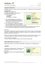
Page 73: ...the CLEAR signal is activated the internal count goes back to 0 Parameters Clear Enable If selected this enables the request to clear in order to restart the counter setting output Q to 0 FALSE It als...

Page 74: ...d the output is set to 1 TRUE on the input signal s rising edge where it remains for the set time which can be extended for as long as the input stays at 1 TRUE In Out T T T If not selected the logic...

Page 75: ...utput follows the signal on the input However if this is 1 TRUE for longer than the set time the output changes to 0 FALSE T In Out T T T Parameters Time The delay can be set to between 10 ms and 1093...

Page 76: ...ng edge at the end of which the output changes to 1 TRUE if the input is 1 TRUE where it remains for as long as the input stays at 1 TRUE In Out T T If not selected the logic is inverted the output is...

Page 77: ...ated with a rising edge To disable muting set Enable to 0 FALSE In this mode the falling edge disables Muting regardless of the condition If Enable Only is selected Muting cannot be disabled but Enabl...

Page 78: ...cted it enables the possibility of enabling or not enabling the Muting function Otherwise the Muting function is always enabled There are two Enable modes Enable Disable and Enable Only If Enable Disa...

Page 79: ...able muting set Enable to 0 FALSE In this mode the falling edge disables Muting regardless of the condition If Enable Only is selected Muting cannot be disabled but Enable must be set to 0 FALSE in or...

Page 80: ...unlimited within which the Muting cycle must end If the cycle is not complete at the end of this time Muting is immediately discontinued Enable If selected it enables the possibility of enabling or no...

Page 81: ...hem delayed in MANUAL mode use the following scheme Figure 38 Two outputs with one delayed in MANUAL mode Assuming the operating mode of the logical DELAY see DELAY paragraph the application must be t...

Page 82: ...rog output expansion unit 2 double OSSD 485EPA02 485EPA04 eloProg output expansion unit 4 double OSSD 485EPA04 485EPR02 eloProg safety relay unit 2 relays 485EPR02 485EPR04 eloProg safety relay unit 4...

Page 83: ...lated harmonized standards DIN EN ISO 13849 1 DIN EN 62061 DIN EN 61131 2 DIN EN 61496 1 Further realted standards DIN EN 61508 1 DIN EN 61508 2 DIN EN 61508 3 DIN EN 61784 3 Leutkirch 16 February 201...

Reviews: