105U-G Wireless Gateway
User Manual
Page 73
© September 2004
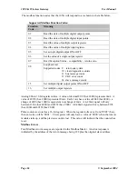
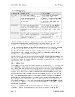
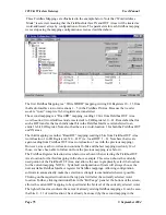
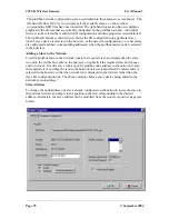
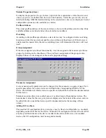
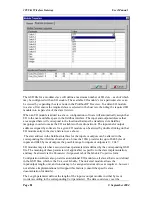
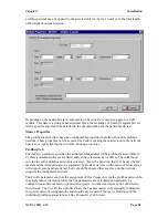
Fieldbus Mapping Types
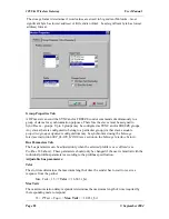
Transfer Mode
Read Mapping
Write Mapping
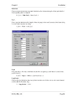
Single Bit
The 105G reads a block of
consecutive bits from Fieldbus OUT
Area and stores each bit in
consecutive I/O Registers, as hex
FFFF or 0000.
The 105G takes the MSB (most
significant bit) of a block of
consecutive I/O Registers, converting
the 16 bit I/O register values into 0 or
1, and writes to consecutive bits of
Fieldbus IN Area.
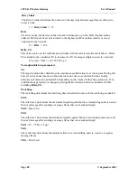
Byte (8-bit)
The 105G reads consecutive bytes
(8-bit values) from Fieldbus OUT
Area and stores each byte in the most
significant 8-bits of a consecutive I/O
register.
The 105G takes the most significant
8-bits of consecutive I/O registers
and writes them to consecutive bytes
(8-bit values) of the Fieldbus IN area.
Word (16-bit)
The 105G reads consecutive words
(2x8-bit values) form Fieldbus OUT
Area and stores each word in a
consecutive I/O Register.
The 105G takes consecutive I/O
registers and writes them to
consecutive words (2x8-bit values) of
Fieldbus IN Area.
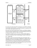
“Word” transfer mode offers no compression, but rather a direct transfer of 16-bit registers
between Radio Interface and Fieldbus Interface. This mode would suit the transfer of
registers containing pulse counts or analog values with no loss of resolution.
“Byte” transfer mode operates on only the most significant BYTE (the first 8 bits) of Radio
Interface registers, but allows these bytes to be consecutively packed in the Fieldbus
Interface. This mode would suit the transfer of analog values in low-resolution, in cases
where I/O space is at a premium. Byte
Address Mode
is recommended when using byte
transfer mode (see Address Mode section below).
Bit transfer mode operates on only the most significant BIT of Radio Interface registers, but
allows these bits to be consecutively packed in the Fieldbus Interface. This mode would suit
the transfer of digital I/O in cases where it is not desirable (or possible) to use a whole 16-bit
register just to store a 0 or 1 value.
4.8.3
Address Mode
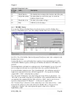
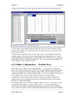
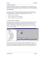
Configuration software allows the Fieldbus Interface IN and OUT areas to be addressed as an
array of 8-bit bytes (
Byte Address Mode
) or an array of 16-bit words (
Word Address Mode
).
The address mode may be required to change depending on the transfer mode, the protocol,
or the particular host device. The Address Mode option is included so that the configuration
software can be setup to use the same I/O addressing method used by the host device. The
actual structure of I/O in this database can only be physically altered via the transfer mode.
The Fieldbus Interface IN and OUT areas are simply a block of I/O memory, exchanged
according to the configured protocol. For example, with a Profibus slave that supports 244
bytes of inputs, the fieldbus interface IN area could be addressed either as byte locations 1 to
244 or as word locations 1 to 122. Note that in either case, the underlying database structure
is unchanged, the difference is limited to the Fieldbus IN/OUT Area address that is displayed
by configuration software.
Certain protocols have an inherent or preferred byte or word structure – for example,
Modbus is a protocol that usually operates on 16-bit (word) registers. Consequently,

