page 2
Technical Manual TAR x700-2
P1
9=
1
P1
9=
2
P1
9=
3
P1
9=
4
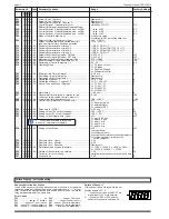
Parameter-#
Parameter Function
Range
Factory Settings
P01
.... x . x .x .x....- ....... Actual Value of Sensor 1 ...................................................Display only! .....................................................-
P02
............x .x....-
.......
Actual Value of Sensor 2 ...................................................Display only! .....................................................-
P03
................x....- ....... Differential Value Sensor 1/Sensor 2 ................................Display only! .....................................................-
P04
.... x . x .x .x....- ....... Control Setpoint 1
(absolute value)
or ..............................Limited by P16/P17 .........................................0°C
Differential Setpoint (depends on Operating Mode)
P05
.... x . x .x .x....- ....... Control Setpoint 2 (
absolute/relative, dep. on P08
) .........." / resp. ± 100 ...................................................0°C
P06
.... x . x .x .x....- ....... Control Setpoint 3 (
absolute/relative, dep. on P08
) .........." / resp. ± 100 ...................................................0°C
P07
.... - .. x .x .- ....- ....... Control Setpoint 4 (
absolute/relative, dep. on P08
) .........." / resp. ± 100 ...................................................0°C
P08
.... x . x .x
.
- ....-
.......
Mode of Control Setpoints 2-4 ..........................................1= absolute value .............................................1
2= relative to P04 (
switching distance)
P09
.... x . x .x
.
x....88 ..... Setpoint-Offset (for day/night mode) .................................-100...+100°C ...................................................0
Amount all setpoints will be shifted after OK 1
(-148...+212°F)
resp. the internal clock has been activated.
P10
.... x . x .x .x....88 ..... Switching characteristic of relay K1 ..................................1=RE, 2=FR, 3=HT ...........................................1
P11
.... x . x .x .x....88 ..... Switching characteristic of relay K2 ..................................1=RE, 2=FR (not TAR 1700), 3 = HT ...............1
P12
.... x . x .x .x....88 ..... Switching characteristic of relay K3 ..................................1=RE, 2=FR (not TAR 1700), 3 = HT ...............1
P13
.... - .. x .x .- ....88 ..... Switching characteristic of relay K4 ..................................1=RE, 2=FR, 3=HT ...........................................1
P14
.... x . x .x .x....88 ..... Setpoint-shift (day/night mode) ON time ...........................0...235, oFF ......................................................oFF
P15
.... x . x .x .x....88 ..... Setpoint-shift (day/night mode) OFF time .........................0...235, oFF ......................................................oFF
P16
.... x . x .x .x....88 ..... Maximum setpoint value adjustable by P04 ......................P17...+300°C ....................................................+50°C
P17
.... x . x .x .x....88 ..... Minimum setpoint value adjustable by P04 .......................-110°C...P16 ....................................................-50
P18
.... x . x .x .x....88 ..... Hysteresis of Control Setpoints 1 - 4 ................................0,2...20 .............................................................2.0
P19
.... x . x .x .x....
70
..... Operating Mode ................................................................1 = 3 Alarm ........................................1
2 = 4 Stages
3 = Double 3-Stages
4 = Differential control
P20
.... x . x .x
.
x....88 ..... Minimium Idle Time (all relays) .........................................0...59 min ..........................................................0
P21
.... x . x .x .x....-- ...... Remaining time of alarm delay .........................................Display only !
P22
.... x . x .x .x....-- ...... Remaining time OK-input delay ........................................Display only !
P23
.... x . x .x .x....88 ..... Calibration of Sensor 1 .....................................................-10,0...+10,0 ....................................................0
P24
.... x . x .x .x....88 ..... Calibration of Sensor 2, switch oFF ..................................-10,0...+10,0, oFF .............................................0
P25
.... x . x .x .x....70* ... Sensor Type and Kind of Degrees ....................................1 = TF 201 (°C) ................................................1
2 = TF 201 (°F)
3 = Pt1000 (°C).
4 = Pt1000 (°F)
P26
.... x . x .x .x....88 ..... Alarm delay .......................................................................1...99 min ..........................................................5
P27
.... x . x .x .x....88 ..... Upper alarm limit
(relative, in relation to the
..................0...100 ..............................................................100
current, possibly shifted Control Setpoint 1)
P28
.... x . x .x .x....88 ..... Lower alarm limit
(absolute value)
....................................-100...+300°C ...................................................-100
P29
.... x . x .x .x....88 ..... Control input (Optocoupler Input) DI/OK 1 ........................oFF ...................................................................oFF
1 = day/night mode
2 = external alarm
3 = controller OFF
P30
.... x . x .x .x....88 ..... Delay time for DI/OK 1 ......................................................0...99 min ..........................................................2
P31
.... x . x .x .x....88 ..... Analog output: 10V output voltage at ................................-100...+300°C ...................................................50
P32
.... x . x .x .x....88 ..... Analog output: 0V output voltage at ..................................-100°C...P31 .....................................................-50
P33
.... x . x .x .x....88 ..... Analog output: Integral time (I-part) ..................................oFF ...................................................................oFF
1 = appr. 0,25 min
2 = appr. 0,5 min
3 = appr. 1 min
4 = appr. 2 min
5 = appr. 4 min
P34
.... x . x .x .x....88 ..... Analog output: Mode .........................................................oFF ...................................................................oFF
1= proportional
2= inversely proport.
3= proportional, relative to the current setpoint
4= inversely proport., relative to the
current setpoint
P35
.... x . x .x .x....- ....... Real time clock: Hours .....................................................0...23
P36
.... x . x .x .x....- ....... Real time clock: Minutes ..................................................0...59
P37
.... x . x .x .x....- ....... Real time clock: Seconds .................................................Display only !
P38
.... x . x .x .x....88 ..... Data transmission speed (Baudrate) ................................1 = 1200, 2 = 2400, 3 = 4800, 4 = 9600 ...........4
5 = 19200, 6 = 28800, 7 = 57600
P39
.... x . x .x .x....88 ..... Adress of the controller in a network .................................1...78 ................................................................78
P40
.... x . x .x .x....- ....... Current error + error listing................................................multiple errors present: scroll by up/down keys
P41
.... x . x .x .x....- ....... Access Code .....................................................................0...99 ................................................................0
Code
x = Functions available in this mode,
without "x" = parameters invisible
Failure Display / Failure handling
Sensor short circuit or broken
If one of the sensors is broken, disconnected or hot-wired, or the value
is located outside of the specified range, the display shows "- - -" at first.
After 1 minute the display flashes and shows an error code. The alarm
relay will be activated at the same time.
Error Codes
E00 ...........................................ok
E01 ................. sensor F1 broken
E02 ...........sensor F1 short circuit
E03 ...sensor F1 overtemperature
E04 ....sensor F1 low temperature
E05 .................. sensor F2 broken
E06 ...........sensor F2 short circuit
E07 ...sensor F2 overtemperature
E08 .....sensor F2 low temperature
E09 ........ failure at the digital input
Failure of Sensor 1
If this sensor fails, all relays will drop out.
Display shows "oFF" if:
1. ...controller unit is switched OFF via
digital input OK1 or via network.
2. ...you select P02 or P24 and the
evaporator sensor is switched off.


