Technical Manual TAR x700-2
page 5
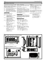
Dimensions / Connection TAR 3700-2
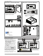
Temperature probe connection
Dimensions / Connection TAR 5700-2
35
(1
.38
)
59 (2.32)
26 (1.02)
39 (1.54)
Panel housing dep. on DIN 43700/IEC 61554
Cut-out:
92 x 45 mm (b x h)
Tolerances max:
+0,8 (b), +0,6 (h)
45
(1
.77
)
49
(1
.93
)
1
31
1 2 13
1 4 15
2
3
2 4 25
4
5 6
7 8
9 10
1 1
2 6 27
2 8 29
3 0
1
1 6 17
1 8 19
2 0 21
2 2 23
mains
Relay K1
Relay K2
Relay K4
(Alarm)
pr
ob
e
F2
pr
ob
e
F1
Relay K3
RS
485
ND
O
1
3
2
4
6
5
8
7
N
TAR 3700-2
N
L
L
L
O K1
A C
24
23
DO
0-1
0V
O
UT
D C
26
25
27
16
13
11
9 10
12
15
14
17 18 19
35
28 29 30 31 32 33 34
36 37 38
DI 1
RS
485
24V AC
ND
O
DO
RS
485
DO
ND
O
Important: use double-pole
switches only if all controllers are
supplied by the same transformer
Electrical Cabinet
Important: Never connect
the secondary coil of the
transformer to PE!
Danger of destruction!
Attention
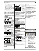
Networking of TAR controllers
All controllers can be networked to a host (PC or
SMZ) via their built-in RS-485-interface.
• Because all units are connected parallel on the
data cable, each unit has its own network address
(
P39
) to ensure a specific communication.
!! Never use address 64 !!
• The data transmission speed is fixed by
P38
, the
default value is 9600 Baud.
• Wiring must be made by standard data cable.
• Shieldings must be connected to the nearest
grounding terminal.
• The unshielded part of the data cable must be as
short as possible.
If networked controllers
(1700-2
types only) are sup-
plied by one transformer only and the single positions
must be switched off, use double-pole switches
only. If not, the unit will be supplied partially over
the shielding of the data connection and continues
operation, depending on the secondary voltage of
the transformer. Please note: If a unit is not supplied,
the PC-software notifies a unit breakdown !
A better way is not to switch-off the supply voltage
but to disable the unit by Digital Input.
Electrical Cabinet
PE
Dimensions in mm,
(in brackets = inches)
Note
Protective Earth
Earth
46
(1
.8
1)
63
(2
.4
8)
91
(3
.5
8)
1 2 3 4 5
7
6
10
8 9
12
11
13 14 15 16 17 18
2
4
P
19
1
3
27
23
22
20 21
25 26
24
29
28
31
30
32
34
33
105 (4.13)
35 36 37 38
TAR
ELREHA
TAR
ELREHA
ELREHA
TAR
76 (3.0)
1
2
3
35 (1.38)
P
4
2/
4/
ELREHA
1/
3/
P
TAR
TAR
ELREHA
ELREHA
TAR
76 (3.0)
1
2
3
35 (1.38)
P
4
119 (4.69)
0..10V DC
unger.
DI 1
92
(3
.62
)
22
7
26
24
25
23
30
29
15
13
14
12
8
11
10
9
K
4
K
3
K
2
DO
GND
NDO
P
E
L
N
23
0V
A
C
50
/6
0H
z
m
ax
.5
V
A
5
6
3
4
2
1
17
20
21
18
K
1
F
2
16
F
1
97
(3
.81
)
M
ade
in
G
erm
an
y
EL
RE
HA
8
119 (4.69)
0..10V DC
DI 1
92
(3
.62
)
22
7
29
30
25
23
24
26
13
15
14
8
9
K
4
K
2
DO
GND
NDO
3
4
5
6
2
L
N
P
E
1
17
23
0V
A
C
50
/6
0H
z
m
ax
.5
V
A
21
K
1
20
18
19
4..20mA
unger.
F
2
16
F
1
97
(3
.81
)
M
ade
in
G
erm
an
y
EL
RE
HA
8
29
3
0
31
16
17
18
19
20
21
24
25
26
22
23
19
(0.75)


