Technical Manual Cold Storage Controllers TKP / TKC x130 - x140
Page 16
Caution
Communication with VPR systems
The TKx controller can be used as intelligent
cold storage controller in co-operation with the
compound control system VPR. In this case, it is
controlled by the VPR. So the TKx need an individual
address („
adress in netwk
“, mode page)
Each controller can be assigned to a certain
compound (Refrigeration or Freezing, „
com-
pound
“, mode page). This enables the VPR to
transmit specific information to the cold storage
controllers assigned to the compound while a
failure occurs.
More detailed information you will find in the tech-
nical manual of the VPR compound system.
Behavior in case of the VPR-function 'Low Power
Optimization'
If this feature is used in the VPR-system, the VPR
can disable the refrigeration functions of the TKx
for a certain time, even though the refrigeration
setpoint is increased. The fans and the heating
continues working, they will be disabled in case
of compound failure only.
All TKx controllers can be networked together
with other ELREHA-control devices. For this duty
ELREHA has developed E-LINK, a transmission
protocol, which will be transmitted on a two-wire
bus-system based on the RS-485-Standard.
With E-LINK, up to
78
controllers are able to
communicate.
Each controller in a network has its individual
address („
adress in netwk
“, mode page). This
adress is necessary for selecting the right controller
while a data package is transmitted on the network
bus. If the controllers are used outside a network,
the address and the parameter „
compound
“ are
of no importance.
Never use address 64 !!
Remote control with SMZ
The TKx can be remote controlled by a SMZ
frontend. In this case all display information and
keypresses will be transmitted.
Configuration / Service via PC
The controllers can be linked via RS 232 or RS
485 interface to a PC where a matching the EL-
REHA-software runs. From there you can change
parameters, save them to the hard disk (download)
and send it to other controllers (upload).
Networking by RS-485-Bus
(E-LINK-Protocol)
Behavior in case of compound failure
If a TKx is assigned to a certain compound and a
disturbance occurs, the unit responds as follows:
●
The solenoid valves will be closed
●
The fan switches off
●
A defrost cycle will be terminated.
A new defrost cycle is only possible when the
compound problem is solved.
To see if this function is released, look
at „
solenoid valve
“ (actual values page).
Data transmission disturbances
If the controller gets no new information from
the VPR, it continues working with the actual
settings.
If there was an order from the VPR to close the
solenoid valves and a technical defect interupts the
data transmission for more than 30 minutes, the TKx
ignores this order and starts working normally.
When data transmission is restored, the TKx will
work again immediately according to the commands
of the VPR.
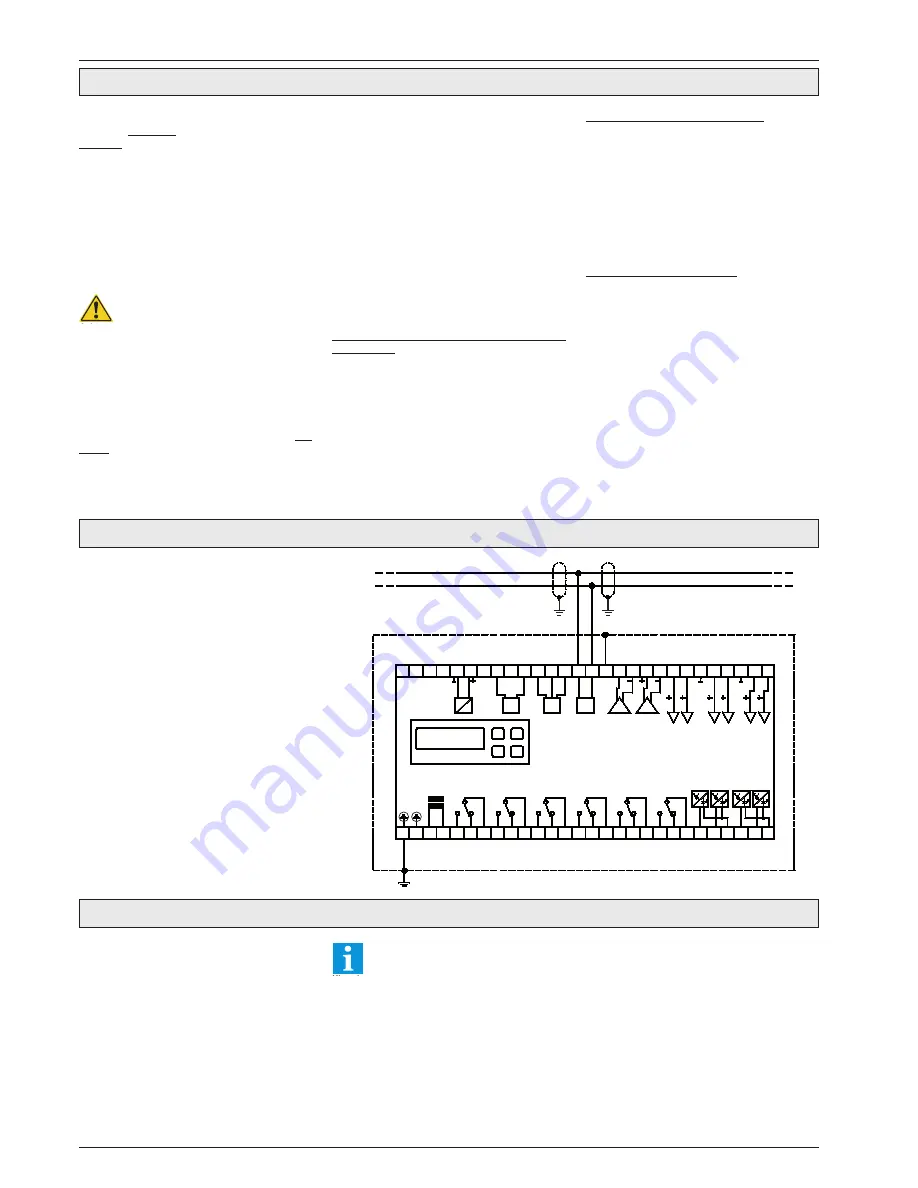
Wiring of data lines
The Line-Interface resp. Line-Bus (RS-485) allows
to connect the controller to a central unit.
Configuration:
●
Use standard "twisted pair" data cable
●
Each module/controller gets an individual
address
●
The best signal-to-noise ratio you get when
each PE connector is grounded the shortest
way
●
The unshielded part of the data cable must be
as short as possible.
The controllers of the TKP 31xx series (from
Soft.Vers. 4.03) are prepared for connecting the
series TAA xx15 Remote Displays.
These displays are able to display the values of
all 6 connectable sensors alternatively.
The TAA display must be connected to the RS-
485-interface "intercom".
Up to 6 TAA xx15 can be connected, each TAA
is able to display any sensor value.
Power Supply
The TAA can be supplied by the TKP-controller
or by an external transformer.
The controllers of the series TKP are
able to supply 2 TAA Remote Displays
max.!
Parameterizing
The TKP controller needs no special settings.
At the TAA the # of the sensor to display must
be set by an incremental switch at the rear side
of the housing.
Display while a defrost cycle
If the controller works in a defrost cycle, the
TAA Remote Display holds the last temperature
value, measured at the beginning of the defrost.
After termination of the defrost event, a real
temperature value will be displayed after the
following preconditions:
●
The measured actual value is less than the
displayed value + 2K
●
After the alarm delay extension is run down
For further information please read the manual
of the used TAA Remote Display.
Connection of Remote Displays
Relais 4
R S
485
Relais 1
1
4
L
3
2
N
5
PE
Netz
TKP 31xx
10
7
6
9
8
14
11
13
12
Relais 2
Relais 3
AC
34
Ve
rso
rg
un
g
un
ge
re
ge
lt
D C
33
38
ND
O
inter-
com
R S
485
DO
35
37
36
OU
T
DO
GN
D
R S
232
IN
42
41
40
39
4..
.20
mA
Au
sg
an
g
0..
.10
V
Au
sg
an
g
Schaltschrank / Electrical Cabinet
OK
1
23
18
15
17
16
19
21
20
22
Relais 5
Relais 6
27
25
24
26
28
OK
4
OK
2
OK
3
51
ND
O
43
46
45
44
F
5
F
6
47
49
48
50
F
1
55
F
3
F
4
F
2
54
53
52
56
Notice


