background image

5

1

3

2

4

ON

7

6

8

ECE

Hole

Jack Socket

Terminal Block

Switch Jumper

Upper Keyhold

Fixing Hole

+ve Terminal

(Red Lead)

Link P51

External Tamper

Lower Fixing

(Blue Lead)

-ve Terminal

Link P1

Power Supply

Reset Jumper

+ve Terminal
(Blue Lead)

(Black Lead)

-ve Terminal

Fixing Hole

Upper Keyhole

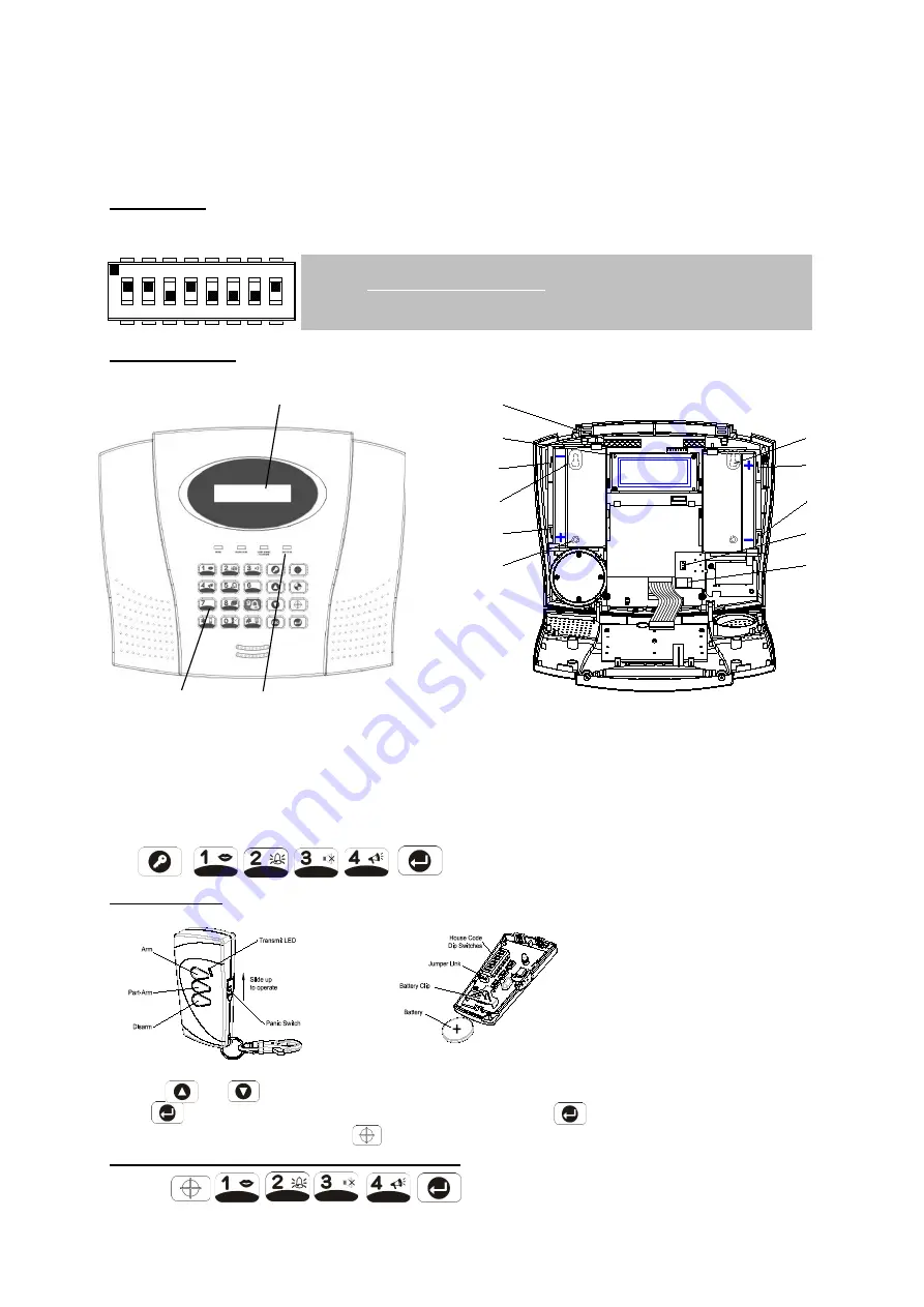
Preparing and installing our new ELRO 10 Zone alarm system. 

We advise to do the pre work, easily on the table, and install later. First unpack all accessories and 

sort the batteries together with the accessories. Unscrew and open all products.  

House Code: 

All products must be programmed with the same house code. In all accessories (not in the Alarm 

panel) you will find a code dipswitch block like in figure: 


The Alarm Panel: 


LCD Display Window 


Keypad             Status LEDs 

Connect battery leads to both back-up batteries: Battery 1 (left): Red lead to +, Blue lead to –, Battery 2 

(right): Blue lead to +, Black lead to –ve battery terminal. 

If the telephone based functionality is to be used then the Control Panel will need connecting to a 

convenient telephone point. Route the cable from the Power Supply Unit up behind, connect the plug to 

the DC power socket in the panel. Take care that during installation and testing on the table, the 

sabotage switch and the back stays free. Now set the Alarm panel in programming mode, by pressing: 


    ‘1 USER SETUP’ is displayed. 


Remote Control:  

The Remote Control is used to Arm, Part-Arm 1-2 and Disarm the system, or give a panic alarm.  


Insert the 3V (CR2032) battery. 

Check if you entered the wished      

house code into the remote, same 

as in the magnet and the PIR.  

We start learning the code to the 

Alarm Panel 

Use the        and         buttons to scroll through the menu until  

‘2. SYSTEM SETUP’

 is displayed. 

Press        and 

‘2-1 Learn House Code’

 will be displayed. Press         again to set the Control Panel to 

receive the House code, press the          on the remote control: house code will be displayed in figures. 

Testing the Alarm Panel by the Remote Control: 

Press:   


       to put the system in the TEST mode. 

Create your own personal code, by putting some switches to on, 
or off. Be sure that you use the same code in all accessories.  

Summary of Contents for Pro Alarm System AP5500

Page 1: ......

Page 2: ...ELRO 10 Zone Pro Alarm System with Voice and Digital Dialer AP5500 Position planning ...

Page 3: ...e Garage PARM1 but not the rest If we are a sleep we only arm the Garage and down floors PARM2 but not the rest If we are away from home Full armed We also can give a sensor being defined as an sensor with Exit Entry Delay For example If we leave home and we want to switch on the alarm on the panel we give the door window magnet E the Exit Entry delay status All other sensors can have the immediat...

Page 4: ... to be used then the Control Panel will need connecting to a convenient telephone point Route the cable from the Power Supply Unit up behind connect the plug to the DC power socket in the panel Take care that during installation and testing on the table the sabotage switch and the back stays free Now set the Alarm panel in programming mode by pressing 1 USER SETUP is displayed Remote Control The R...

Page 5: ...tact consists of two parts a Detector and a Magnet They are designed to be fitted to doors or windows with the Magnet mounted on the moving opening part Mounting the door wind magnet Decide which doors windows are to be protected by fitting Magnetic Contact Detectors usually the front and back doors Additional detectors may also be fitted where required to other vulnerable doors or windows e g gar...

Page 6: ...stall mode Press until you see in the display DISARM READY and the time Now we go into the Program Install mode mentioned further Inst mode Press 1 2 3 4 1 2 3 4 standard Master Password display show 1 USER SETUP First we will change the Master Password Press 1 1 USER 1 SETUP Press display 1 7 MASTER SETUP Press display 1 Password 1234 Press display Enter Password Code NOW PRESS YOUR NEW CODE and ...

Page 7: ... Press to insert a 3 6s pause in the dialing sequence Press to move the cursor left Press to move the cursor right Press to delete the character under the cursor Press and hold to erase the entire phone number Scroll through the menu until 4 3 RECORD VOICE is displayed and press Scroll through the available menu options until the required message type to be recorded is displayed 1 Main Alarm messa...

Page 8: ...ill always be points to improve points Which these are nobody can tell us no better then you We would like to hear from you what your experience was during the preparation installation and the use of this ELRO 10 ZONE PRO ALARM SYSTEM Go to www elro eu and give us your opinion about this ELRO 10 ZONE PRO ALARM SYSTEM Wishes and tips are very welcome You will also find an overview of accessories an...

Reviews: