background image

ELSEMA 

4G Receiver with relay output, G-2025 


Page


13


www.elsema.com


Reset the Password of the GSM receiver to factory default. 


Slide the switch near the SIM card to OFF position and disconnect the power. Press and hold the reset button, 
connect the power and then slide the switch to “ON”. After 6 seconds the Network LED will blink 5-6 times to 
indicate the password has been reset. Release the reset button and do a power cycle. 

This will only reset the password to factory default. It will not change any other settings. All other settings can 
only be changed by PC software or SMS. 


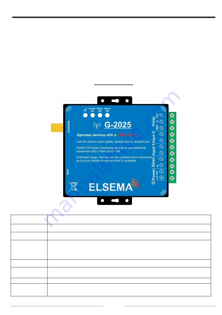
Block Diagram 


Power ON 

Power ON indicator. 

Alarm ON 

The LED lights up when the inputs are triggered and there is alarm condition. 

Relay ON 

The LED lights up when the relay switches ON. 

Network Signal 

Flash every 1 Second: Registering to the mobile network or looking for network 
Flash every 2 Second: Successfully connected to the network. Normal status. 
OFF: Unregistered network or cannot connect to the network.  

Power 

9 - 24 Volts DC. 12v DC Power pack supplied 

Inputs 1 & 2 

Can be used to connect Reed switch, PIR, fire alarm or any other dry contact switch. 
Inputs can be changed to Normally Closed (NC).  

Relay Output 

Common (C) and Normally Open (NO) relay outputs rated at 3A, 240VAC. 

Siren 

DC output to connect siren or flasher lights or any other device. Siren voltage output is 
the supply voltage used to power the GSM receiver.  

Summary of Contents for G-2025

Page 1: ...h Optus All you need is to insert a valid SIM card and program phone numbers of all users using the PC software or through simple SMS text commands When an authorized user makes a call to the receiver...

Page 2: ...eless equipment might interfere with the 4G network signals of the G 2025 and influence its performance Avoid using at Petrol Gas Stations Do not use G 2025 at a petrol gas station Power off the GSM R...

Page 3: ...210xUSB to UART Bridge for example COM3 7 If this driver is not visible install the driver from the USB flash drive included 8 Run the configuration software type in the COM Port number for example CO...

Page 4: ...ttings from the GSM receiver to the PC software 2 Save Settings Save the basic parameter settings to the GSM receiver 3 Import profile Import xls profile All settings can be imported from the GSM rece...

Page 5: ...uthorized number list in xls format from the PC to the configuration software 4 Export xls Export the authorized number list in xls format to the PC under the configuration folder 5 Export csv Export...

Page 6: ...t the start and the end Date and Time of the data which you wish to view 3 Export xls Exports the historical data in xls format to the PC under the configuration folder 4 Export csv Exports the histor...

Page 7: ...GSM receiver try adding in front of the phone numbers or the country code SMS command structure SMS Commands Below are the SMS command needed for the GSM receiver In the examples the default password...

Page 8: ...mbers are mobile numbers of all users who will be using their phones to operate the GSM receiver Serial number is the position of all stored numbers authorized users 001 999 users It is strongly recom...

Page 9: ...receiver 1234ALL Allow access only to authorized numbers calling the GSM receiver o PwdAUT To allow access to authorized numbers only the following SMS command is needed 1234AUT This allows only the...

Page 10: ...low AB Option SMS Confirmation to user A First user B Caller 1st user Caller 0 0 0 1 1 0 1 1 0 means disable 1 means enable Content is the SMS message which the user and the caller will receive E g If...

Page 11: ...or inputs to be active the GSM Receiver should be armed either with SMS or the PC Software Change Digital input 1 from NO to NC Factory default is Normally Open NO o PwdDIN1NC E g To change Input 1 fr...

Page 12: ...iver will always be disarmed E g If the user wishes to change the time to 2 minutes after which input 2 becomes active the following SMS command is needed minimum is 1 minute 1234D002 Power failure SM...

Page 13: ...r ON Power ON indicator Alarm ON The LED lights up when the inputs are triggered and there is alarm condition Relay ON The LED lights up when the relay switches ON Network Signal Flash every 1 Second...

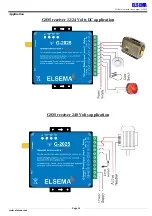
Page 14: ...ELSEMA 4G Receiver with relay output G 2025 Page 14 www elsema com Application GSM receiver 12 24 Volts DC application GSM receiver 240 Volts application...

Reviews: