background image


Limit Switch Adjustment 


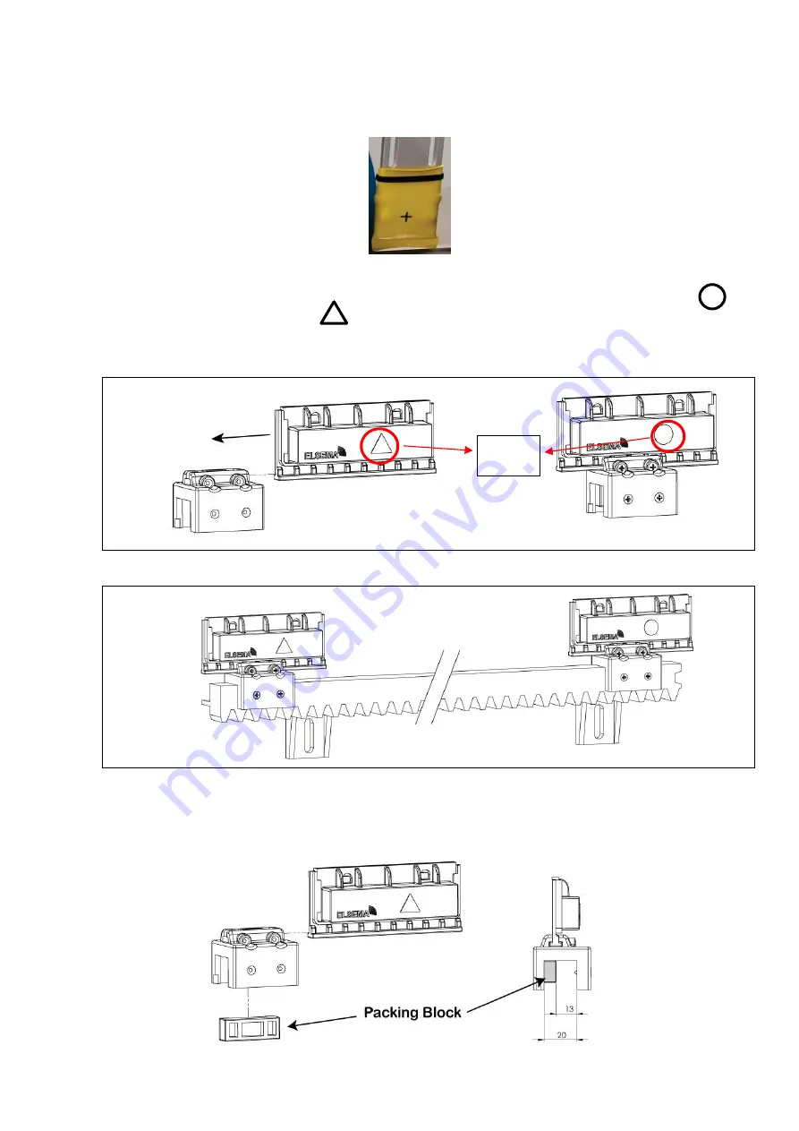
The limit sensor has a + marking indicating the centre of the sensor. Adjust the sensor 
so that the + marking is in the centre of the magnet on the gear rack. 


The 2 x limit magnets should have different marking on them. One should have a         
and the other should have a        . You cannot use the limit magnets if they have the 
same marking. The magnets can be installed on either side (open or close). Please see 
the diagram below to locate the marking on the magnets.


When steel gear rack is used (or gear rack which are much slimmer), you will have to use 
the packing block which comes with the limit switches. Please see the diagram below. 


Polarity 
Marking 

Summary of Contents for INTELLIGENT SLIDER iS1500LV

Page 1: ...HIGH SPEED SLIDING GATE OPENER WITH BATTERY BACK UP Model iS1500LV Elsema s Eclipse Control Card USER MANUAL...

Page 2: ...tions are used Display any necessary signs to indicate any danger areas and automatic operation of the gate or door The operators are not designed to be used in any hazardous areas or areas subject to...

Page 3: ...te base approximately 600mm long x 300 wide x 300mm deep should be laid where the gate operator is to be located IMPORTANT ensure there are gate stops firmly installed in the fully open and closed pos...

Page 4: ...een the rack teeth and Pinion wheel 3 Once the rack is fixed move the gate and sight the rack moving over the pinion wheel check that most of the pinion wheel meshes with the rack Make sure rack runs...

Page 5: ...g on them One should have a and the other should have a You cannot use the limit magnets if they have the same marking The magnets can be installed on either side open or close Please see the diagram...

Page 6: ...ening Photo Beam P E N C safety input Can be set for N O operation if needed through menu 3 1 PE beam operation modes can be changed through menu 4 2 Control Outputs 12VDC Supplies regulated 12VDC at...

Page 7: ...now be opened by hand To re engage the clutch move the gate by hand into approx the halfway position and turn the knob clockwise until it is very tight If when turning the knob clockwise and it just...

Page 8: ...r will not run inadvertently Gate rolls freely when in manual Gate wheels and guide rollers in good condition Gate stops are installed and in good condition not loose Gate rack is tight correct cleara...

Reviews: