background image

POLARIS 10●15●20●30●40●60●80●100●120●160 

TRIPHASE-TRIPHASE 

Rev. 0

4

 – 

06


December

 2016 

Contents

1

Safety ............................................................................................................................................... 3 

1.1 Safety notes .............................................................................................................................. 3 

1.2 Symbols used in this guide ....................................................................................................... 3 

2

Main Features ................................................................................................................................. 3 

2.1 Summarization .......................................................................................................................... 3 

2.2 Functions and Features ............................................................................................................ 3 

3

Installation....................................................................................................................................... 4 

3.1 Unpack checking ...................................................................................................................... 4 

3.2 Cabinet Outlook ........................................................................................................................ 4 

3.3 Display control panel ................................................................................................................ 6 

3.4 Installation notes ....................................................................................................................... 6 

3.5 External Protective Devices ...................................................................................................... 7 

3.6 Power Cables ............................................................................................................................ 7 

3.7 Power cable connect ................................................................................................................. 9 

3.8 Battery connection .................................................................................................................. 10 

3.9 UPS parallel Installation .......................................................................................................... 11 

3.10 Computer access (CD MUSER4000 optional) ..................................................................... 12 

4

Operation ...................................................................................................................................... 13 

4.1 Operation Modes ..................................................................................................................... 13 

4.2 Turn on/off UPS ...................................................................................................................... 13 

4.3 The TFT Color Display............................................................................................................ 18 

4.4 Parameters Display & Setting ................................................................................................ 21 

4.5 Display Messages/Troubleshooting ....................................................................................... 23 

4.6 Options ................................................................................................................................... 24 

Appendix 1 Specifications ................................................................................................................ 25 

Appendix 2 Problems and Solution ................................................................................................. 29 

Appendix 3 USB communication port definition............................................................................ 30 

Appendix 4 RS232 communication port definition ........................................................................ 30 

Appendix 5 RS485 communication port definition ........................................................................ 31 

Appendix 6 Dry contact communication port definition ............................................................... 31 

Appendix 7 REPO instruction........................................................................................................... 32 

Appendix 8 Accessories ................................................................................................................... 32 

Appendix 9 Efficiency Chart ............................................................................................................. 33 

Publish statement 

Thank you for purchasing this series UPS. 

This series UPS is an intelligent, three phase in Three phase out, high frequency online UPS designed by our R&D team who is with years 

of  designing  experiences  on  UPS.  With  excellent  electrical  performance,  perfect  intelligent  monitoring  and  network  functions,  smart 

appearance, complying with EMC and safety standards, The UPS meets the world’s advanced level.   

Read this manual carefully before installation 

This manual provides technical support to the operator of the equipment. 

All rights reserved. 

The information in this document is subject to change without notice. 

Summary of Contents for POLARIS 10

Page 1: ...Electrical System for Continuity P P P Polaris 3 3 3 3Phase 10 10 10 10 16 16 16 160 0 0 0Kva INSTRUCTION MANUAL ...

Page 2: ...2 Problems and Solution 29 Appendix 3 USB communication port definition 30 Appendix 4 RS232 communication port definition 30 Appendix 5 RS485 communication port definition 31 Appendix 6 Dry contact communication port definition 31 Appendix 7 REPO instruction 32 Appendix 8 Accessories 32 Appendix 9 Efficiency Chart 33 Publish statement Thank you for purchasing this series UPS This series UPS is an ...

Page 3: ... location nearby heat Vibration Area with possibility to get the UPS crashed Area with erosive gas flammable gas excessive dust etc 8 Keep ventilations in good conditions otherwise the components inside the UPS will be over heated which may affect the life of the UPS 1 2 Symbols used in this guide WARNING Risk of electric shock CAUTION Read this information to avoid equipment damage 2 MAIN FEATURE...

Page 4: ...tends the life of the batteries and guarantees fast charging LCD Display With LCD plus LED displays the user may easily get UPS status and its operational parameters such as input output voltage frequency load battery and ambient temperature etc Intelligent Monitoring Function Via optional SNMP Card you may remotely control and monitor the UPS EPO Function The series UPS may be completely shut off...

Page 5: ...card 13 Maintenance switch its cover 14 Intelligent Slot 2 SNMP card Relay card 15 O P Switch 16 Ground 10 20KVA Rear View terminal block without cover 1 TFT color display panel 2 Intelligent Slot 1 SNMP card Relay card 3 Intelligent Slot 2 SNMP card Relay card 4 Power Switch 5 Dry contact port 6 USB port 7 RS485 port 8 REPO port 9 RS232 port 10 Parallel port 1 2 11 Maintenance switch its cover 12...

Page 6: ...vironment where the temperature is within the required specs Temperature is a major factor in determining battery life and capacity In a normal installation the battery temperature is maintained between 15 C and 25 C Ke ep batteries away from heat sources or main air ventilation area etc WARNING Typical battery performance data are quoted for an operating temperature between 20 C and 25 C Operatin...

Page 7: ...etic circuit breaker with an IEC 60947 2 trip curve C normal for 125 of the current as listed below 3 6 Power Cables The cable design shall comply with the voltages and currents provided in this section Kindly follow local wiring practices and take into consideration the environmental conditions temperature and physical support media WARNING Upon starting Please ensure that you are aware of the lo...

Page 8: ... 500Vdc 200A 500Vdc 2x 200A 500Vdc UPS MODEL 80KVA 2X40KVA 100KVA 3X30KVA 120KVA 3X40KVA 160KVA 4X40KVA INPUT breaker 2x 3P 80A 400Vac 3x 3P 63A 400Vac 3x 3P 80A 400Vac 4x 3P 80A 400Vac OUTPUT breaker 2x 3P 100A 400Vac 3x 3P 63A 400Vac 3x 3P 100A 400Vac 4x 3P 100A 400Vac BY PASS breaker 2x 3P 100A 400Vac 3x 3P 63A 400Vac 3x 3P 100A 400Vac 4x 3P 100A 400Vac Internal Battery Fuse 2x 200A 500Vdc 3X 2...

Page 9: ...y negative Input phase A L1 input phase B L2 input phase C L3 input Neutral line output phase A L1 output phase B L2 output phase C L3 output and battery Neutral line battery positive battery negative There are 3 connectors of GROUND under the terminal block Choose appropriate power cable Refer to the table above and pay attention to the diameter of the connection terminal of the cable that should...

Page 10: ... are called positive batteries and that between neutral and cathode are called negative ones External battery connections for long run units 10 15 20 30 60 100KVA 40 80 120 160KVA Note The BAT of the UPS connect poles is connected to the anode of the positive battery the BAT N is connected to the cathode of the positive battery and the anode of the negative battery the BAT is connected to the cath...

Page 11: ... and double insulated control cables available must be interconnected in a ring configuration between UPS units as shown below The ring configuration ensures high reliability of the control 3 9 3 Requirement for the parallel system A group of paralleled UPS behaves as one large UPS system but with the advantage of presenting higher reliability In order to assure that all UPS are equally utilized a...

Page 12: ...the USB port on the UPS Open the software Muser4000 click system button A window of Software Parameter Setting comes out as below COM choose according to the UPS baud rate choose 9600 protocol choose HIP then save this setting On the main page of Muser4000 click the button of Append then goes to a window of Append equipment Put the UPS name into Equipment Name and UPS ID address into Equipment add...

Page 13: ...ot synchronized with the bypass AC source the static switch will perform a transfer of the load from the inverter to the bypass with power interruption to the critical AC load This is to avoid paralleling of unsynchronized AC sources This interruption is programmable but typically set to be less than an electrical cycle e g less than 15ms 50Hz or less than 13 33ms 60Hz ECO Mode When the UPS is at ...

Page 14: ...of the UPS will be shown on the LCD display 4 2 2 Test procedure CAUTION The UPS is operating normally It may take 60 seconds to boost up the system and perform self test completely Switch off the MAINS to simulate utility failure the rectifier will turn off and the battery should feed the inverter without interruption At this time the LED of battery should be turned on Switch on the MAINS to simu...

Page 15: ... UPS powers from the static bypass instead of the maintenance bypass then the bypass LED will light up Switch OFF the maintenance bypass breaker then the output is supplied by the static bypass of the UPS Put on the maintenance switch cover The rectifier will operate normally after 30 seconds If the inverter works normally the system will be transferred from bypass mode to normal mode Green LED tu...

Page 16: ...The UPS shuts down To completely isolate the UPS from AC Mains all input switches of Utility shall be completely off which includes the ones for rectifier and bypass The primary input distribution panel which is often located far away from the UPS area so a label should be posted to advise service personnel that the UPS circuit is under maintenance WARNING The internal capacitors are not completel...

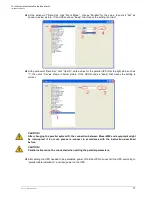
Page 17: ...t side such as 1 then click Set as shown in below picture If the UPS sounds a beep that means the setting is correct CAUTION After changing the parallel system ID the connection between Muser4000 and equipment might be interrupted If it occurs please re connect in accordance with the instruction described before CAUTION Parallel cable cannot be connected when setting the parallel parameters After ...

Page 18: ...color Display 1 LED indicator 2 TFT color display 3 Scroll button 4 Off button 5 On button Overview of the operating panel of the UPS Introduction CAUTION The display provides more functions than those described in this manual 1 Main Display 2 Data Display 3 Data Input Display 4 Data Output Display ...

Page 19: ...LARIS 10 15 20 30 40 60 80 100 120 160 TRIPHASE TRIPHASE Rev 04 06 December 2016 19 5 Data Battery Display 6 Data Load Display 7 Data Inside Display 8 Info Display 9 Setting User Display 10 Record Display ...

Page 20: ...0min Test for 10Min EOD Test until End Of Discharge WITH SOFTWARE MUSER4000 After setting Test Time push Battery Test and immediately the Battery test start The yellow Battery Led turn on and buzzer bip 1 per sec On the Muser monitor show in red square there is Battery Supply indication When the test finish the battery Led turn off and the Inverter Green led turn on the buzzer silence and in the M...

Page 21: ...he Inverter SELECT OFF If you press this key combination in the setting page you can enter into the input interface for maintenance password restricted only for authorized technicians USERS INTERFACE Available views at the user level are those described in section 4 3 pictures 1 to 12 The enable settings are those shown in picture 9 AUTORIZED TECHNICIANS INTERFACE Available to technicians and auth...

Page 22: ...tery EOD If the Test Battery is setting for 10min and backup time is lower than 10 min MBT ABT Battery Led blinking Display message Fault Bat Low pre warning The Ups goes to Inverter mode Battery Led blinking every 1 sec Buzzer bip every 1 sec Display message Fault Battery EOD Until the battery charge percentage reach about 43 then only the green inverter Led is ON WRONG ROTARY FIELD Input main wr...

Page 23: ...sly Fault LED lit Inverter fault Including Inverter bridge is shorted Beep continuously Fault LED lit Inverter Thyristor short Beep continuously Fault LED lit Inverter Thyristor broken Beep continuously Fault LED lit Bypass Thyristor short Beep continuously Fault LED lit Bypass Thyristor broken Beep continuously Fault LED lit Fuse broken Beep continuously Fault LED lit Parallel relay fault Beep co...

Page 24: ...attery LED lit Mains freq abnormal Once per 2 seconds Battery LED lit Bypass Not Available BPS LED blinking Bypass unable to trace BPS LED blinking Inverter on invalid Reserve inverter not on 4 6 Options SNMP card internal SNMP external SNMP Loosen the 2 torque screws on each side of the card Carefully pull out the card Reverse the procedure for re installation The slot called SNMP supports the ME...

Page 25: ...res and Ground Rated Voltage 380 400 415Vac Power Factor 0 9 Voltage Regulation 1 Frequency Utility Mode 1 2 4 5 10 of the rated frequency optional Battery Mode 50 60 0 1 Hz Crest Factor 3 1 THD 1 with linear load 3 with non linear load Efficiency in normal mode 96 5 97 5 Battery Voltage Standard UPS 120Vdc 10 10 12V 7 9AH Long run backup UPS 96V 108V 120Vdc 16 18 20 pz optional Standard UPS 240Vd...

Page 26: ... Battery Management Noise Suppression Complies with EN62040 2 Alarms Audible Visual Line Failure Battery Low Overload System Fault Display Status LED LCD Line Mode Bypass Mode Battery Low Battery Bad Overload UPS Fault Reading on the LCD Input Voltage Input Frequency Output Voltage Output Frequency Load Percentage Battery Voltage Inner Temperature etc Communication Interface USB RS485 Parallel opt...

Page 27: ...15Vac Power Factor 0 9 0 8 0 9 0 9 Voltage Regulation 1 Frequency Utility Mode 1 2 4 5 10 of the rated frequency optional Battery Mode 50 60 0 1 Hz Crest Factor 3 1 THD 1 with linear load 3 with non linear load Efficiency in normal mode 97 5 Battery Voltage Standard UPS 240Vdc 20 20 12V 7 9AH Long run backup UPS 192 204 216 228 24 0Vdc 32 34 36 38 40 pz optional Standard UPS 120Vdc 10 10 12V 7 9AH...

Page 28: ...ession Complies with EN62040 2 Alarms Audible Visual Line Failure Battery Low Overload System Fault Display Status LED LCD Line Mode Bypass Mode Battery Low Battery Bad Overload UPS Fault Reading on the LCD Input Voltage Input Frequency Output Voltage Output Frequency Load Percentage Battery Voltage Inner Temperature etc Communication Interface USB RS485 Parallel optional Coupler dry contact Intel...

Page 29: ...t indicate any failure but output do not have voltage Output cable does not well connected Output breaker do not switch on Make sure the output cable is well connected Switch on the output breaker 4 Utility LED is flashing Utility voltage exceeds UPS input range If the UPS operates at battery mode please pay attention to the remaining backup time needed for your system 5 Battery LED is flashing bu...

Page 30: ...bit 1bit Parity check none CAUTION USB RS232 and RS485 interface cannot be used at the same time you can only use one of them at one time APPENDIX 4 RS232 COMMUNICATION PORT DEFINITION Definition of Male port Connection between PC RS232 port and UPS RS232 port PC RS232 PORT UPS RS232 PORT SIGNAL DESCRIPTION Pin 2 Pin 2 UPS send PC receive Pin 3 Pin 3 PC send UPS receive Pin 5 Pin 5 Signal Ground A...

Page 31: ...running parameters Timing off on setting Battery environment temperature monitoring Charging voltage modulation depending on batteries temperature CAUTION USB RS232 and RS485 interface cannot be used at the same time you can only use one of them at one time APPENDIX 6 DRY CONTACT COMMUNICATION PORT DEFINITION with Optoisolator Definition of Male port Instruction UPS INSTRUCTION STATUS Pin 1 UPS Ba...

Page 32: ...emergency stop switch Dry contact signal and normally open not provided can be installed in a remote location and connection through simple wires to the REPO connector The remote switch can be connected to several UPS in a parallel architecture allowing the user to stops all units at once APPENDIX 8 ACCESSORIES Check if the following accessories are present in the packaging TYPE POLARIS 10 160 Use...

Page 33: ...E Rev 04 06 December 2016 33 APPENDIX 9 EFFICIENCY CHART Below the table and graphics for efficiency data Model Load 10kVA 15kVA 20kVA 30kVA 40kVA 25 94 9 97 2 97 3 96 8 97 1 50 96 5 97 5 97 5 97 5 97 5 75 96 9 97 5 97 5 97 6 97 5 100 96 9 97 7 97 7 97 6 98 3 ...

Page 34: ...Naicon srl Via il Caravaggio 25 Trecella I 20060 Pozzuolo Martesana Milano Italy Tel 39 02 95 003 1 Fax 39 02 95 003 313 www naicon com e mail naicon naicon com ...

Reviews: