POLARIS 10●15●20●30●40●60●80●100●120●160
TRIPHASE-TRIPHASE
Rev. 04 – 06 December 2016
9
3.7 Power cable connect
Once the equipment has been finally positioned and secured, connect the power cables as described in
the following procedure.
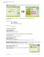
Verify the UPS is totally isolated from its external power source and also all power isolators of the UPS
are open. Check to see if they are electrically isolated, and post any necessary warning signs to prevent
their inadvertent operation. Remove the cover of terminals for wiring easily.
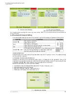
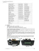
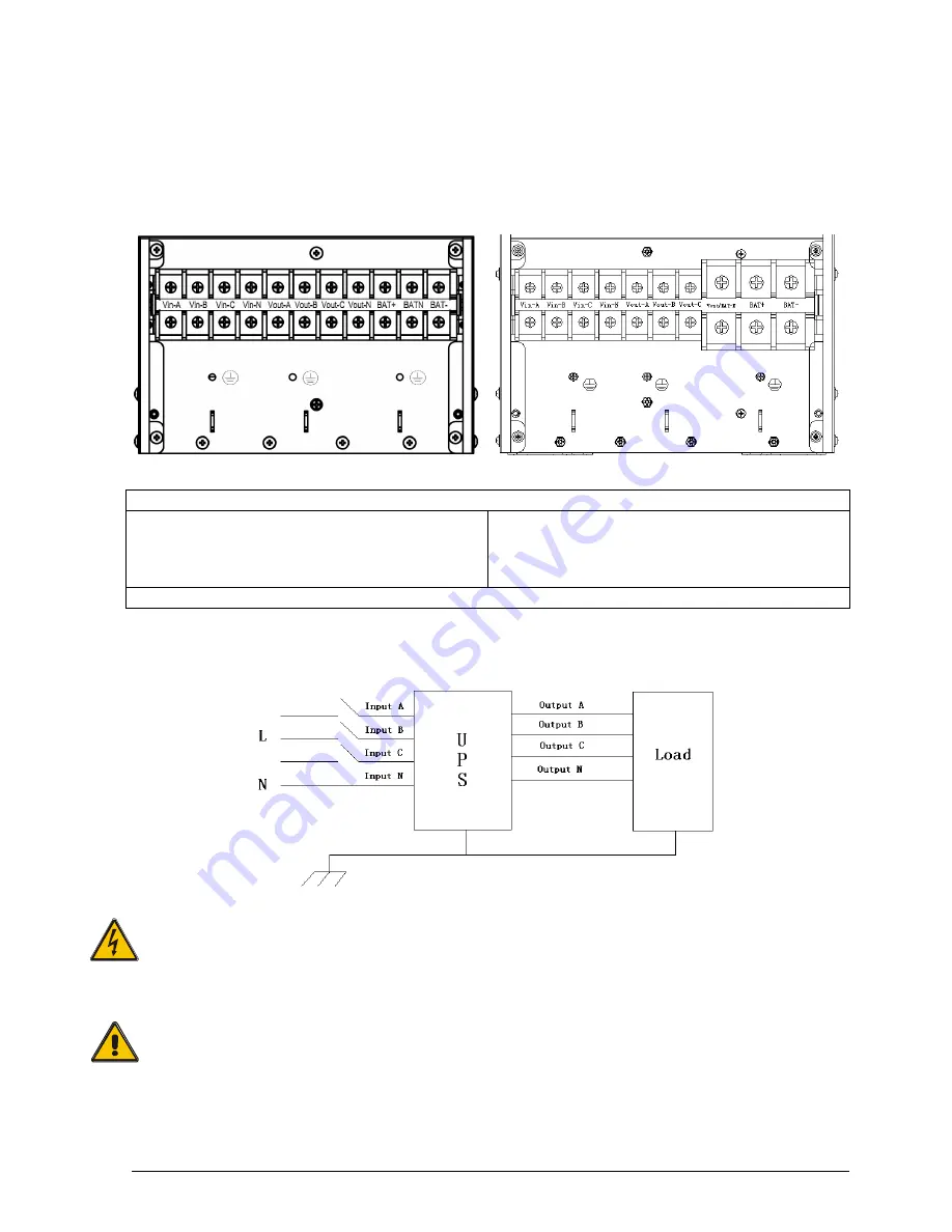
10-20KVA
30-160KVA
Terminal sequence from left to right:
Input phase A(L1), input phase B(L2), input phase
C(L3), input Neutral line, output phase A(L1), output
phase B(L2), output phase C(L3), output Neutral line,
battery positive, battery Neutral, battery negative.
Input phase A(L1), input phase B(L2), input phase
C(L3), input Neutral line, output phase A(L1), output
phase B(L2), output phase C(L3), output and battery
Neutral line, battery positive, battery negative.
There are 3 connectors of GROUND under the terminal block.
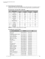
Choose appropriate power cable. (Refer to the table above) and pay attention to the diameter of the
connection terminal of the cable that should be greater than or equal to that of the connection poles;
WARNING!
If the load equipment is not ready to accept power on the arrival of the commissioning engineer
then ensure that the system output cables are safely isolated at their ends.
Connect the safety earth and any necessary bonding earth cables to the copper earth screw
located on the floor of the equipment below the power connections. All cabinets in the UPS
must be grounded properly.
CAUTION!
The earthing and neutral bonding arrangement must be in accordance with local and national
codes of practice.


