background image

13

Maintenance

Weather Station P04-KNX-GPS

 • Status: 01.04.2020 • Errors excepted. Subject to technical changes.

4.

Maintenance

WARNING!
Risk of injury caused by components moved automatically!

The automatic control can start system components and place people
in danger (e.g. moving windows/awnings if a rain/wind alarm has been
triggered while cleaning).

Always isolate the device from the mains for servicing and 
cleaning.

The device must regularly be checked for dirt twice a year and cleaned if necessary. In
case of severe dirt, the sensor may not work properly anymore.

ATTENTION

The device can be damaged if water penetrates the housing.

Do not clean with high pressure cleaners or steam jets.

Summary of Contents for P04-KNX-GPS

Page 1: ...P04 KNX GPS Weather Station Item number 71230 Installation and Adjustment EN ...

Page 2: ......

Page 3: ...ent direction of the brightness sensor 7 2 4 Installing the weather station 8 2 4 1 Attach mount 8 2 4 2 Assembly with Mounting Arm Fix 8 2 4 3 Attaching and connecting the device 11 2 5 Instructions for assembly and initial start up 12 3 Addressing the equipment 12 4 Maintenance 13 5 Transfer protocol 14 5 1 List of all communications objects 14 6 Parameter setting 15 6 0 1 Behaviour on power fai...

Page 4: ...leshooting of the device must only be carried out by a competent electrician Safety advice Safety advice for working on electrical connections components etc DANGER indicates an immediately hazardous situation which will lead to death or severe injuries if it is not avoided WARNING indicates a potentially hazardous situation which may lead to death or severe injuries if it is not avoided CAUTION i...

Page 5: ...precipitation but not mist or dew When the rain or snow stops the sensor is soon dry again and the precipitation warning ends Temperature measurement Configuration is made using the KNX software ETS The product file can be down loaded from the Elsner Elektronik website on www elsner elektronik de in the Ser vice menu 1 0 1 Deliverables Sensor Connection cable approx 10 m with plug and connecting t...

Page 6: ...V DC max 90 mA Bus current max 10 mA Data output KNX BCU type Integrated microcontroller PEI type 0 Group addresses max 2000 Assignments max 2000 Communication objects 28 Temperature sensor Measurement range 30 C 50 C Resolution 0 1 C Wind sensor Measurement range 0 m s 35 m s Resolution 0 1 m s Accuracy 15 of the measurement value when incoming flow is 45 315 Frontal incoming flow corresponds to ...

Page 7: ...ay occur after publication of these operating instructions 2 2 Installation location Select an installation position on the building where the sensors can measure wind rain and sunshine without hindrance No structural elements should be mounted above the weather station from which water could continue to drop on the precipita tion sensor even after it has stopped raining or snowing The weather sta...

Page 8: ...s structures construction parts etc below to the sides and in front of the de vice 60 cm Fig 2 The device must be attached to a vertical wall or a pole Place the supply line in a loop before leading it into the wall or junction box This will allow rain to drip off and not drain into the wall or box Wall or pole 90 Fig 3 The device must be mounted in the horizontal transverse direction Horizontal F...

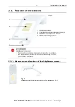
Page 9: ...r Remove the protective transport sticker after installation Do not touch the sensor on the wind measuring element on bottom recessed 2 3 1 Measurement direction of the brightness sensor 1 Brightness sensor 2 Precipitation sensor area with tracks 3 Position of temperature sensor 4 Wind measuring element 3 2 1 4 Fig 5 Fig 6 Measurement directed vertically to the device surface ...

Page 10: ...2 Assembly with Mounting Arm Fix With the Mounting Arm Fix the weather station can be flexibly mounted on the wall Only use suitable fixing material screws dowels to fix the wall installation plate and make sure that the subsurface is stable Fig 7 Front view Use two screws to attach the mount to the wall Use the fastening material dowels screws that is suitable for the base Make sure that the arro...

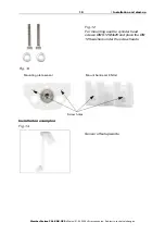
Page 11: ... mounting plate Fix Affix sensor mounting plate Fig 9 Mounting plate Sensor Wall mounting plate 34 mm 54 mm Fig 10 Hole diameter 6 2 mm Fig 11 Schema sequence screw fastening Screw the sensor mounting plate onto the boom with the countersunk screw DIN 7991 M8x10 Place the Schnorr tooth lock washers between the mounting plate and the boom ...

Page 12: ... Errors excepted Subject to technical changes Installation examples Fig 12 For mounting use the cylinder head screws DIN 912 M4x25 and place the DIN 125 washers under the screw heads Mounting plate sensor Mount Suntracer KNX sl Screw holes Fig 13 Fig 14 Sensor offset upwards ...

Page 13: ...hing and connecting the device Fig 15 Sensor offset downwards Fig 16 Sensor offset to the right or the left Fig 17 1 Slide the device onto the mounting from above 2 Tighten the screw of the mount to secure the device 3 Screw the M8 connectors of the connection cable onto the connection socket on the bottom side of the device 3 2 1 ...

Page 14: ... voltage has been applied the device will enter an initialisation phase lasting a few seconds During this phase no information can be received or sent via the bus 3 Addressing the equipment The equipment is delivered ex works with the bus address 15 15 255 You program a different address in the ETS by overwriting the address 15 15 255 or teach the device using the programming button The programmin...

Page 15: ...ace people in danger e g moving windows awnings if a rain wind alarm has been triggered while cleaning Always isolate the device from the mains for servicing and cleaning The device must regularly be checked for dirt twice a year and cleaned if necessary In case of severe dirt the sensor may not work properly anymore ATTENTION The device can be damaged if water penetrates the housing Do not clean ...

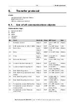
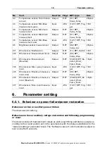
Page 16: ...es 27 Time Input Output RWCT 10 1 DPT_Ti meOfDay 3 Bytes 28 Date and time query Input WC 1 017 DPT_Trig ger 1 Bit 30 Location Northern latitude Output R CT 14 7 DPT_ Value_AngleDeg 4 Bytes 31 Location Eastern longitude Output R CT 14 7 DPT_ Value_AngleDeg 4 Bytes 34 Rain Switching output Output R CT 1 1 DPT_Switch 1 Bit 35 Rain Switching output with fixed delays Output R CT 1 1 DPT_Switch 1 Bit 36...

Page 17: ...t WC 1 017 DPT_Trig ger 1 Bit 46 Temperature sensor Minimum measurement Output R CT 9 1 DPT_ Value_Temp 2 Bytes 47 Temperature sensor Maximum measurement Output R CT 9 1 DPT_ Value_Temp 2 Bytes 48 Temperature sensor Min Max measurement reset Input WC 1 017 DPT_Trig ger 1 Bit 95 Brightness sensor measurement Output R CT 9 4 DPT_ Value_Lux 2 Bytes 271 Wind sensor Malfunction Output R CT 1 1 DPT_Swit...

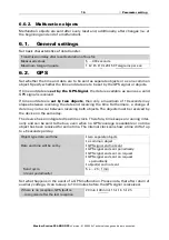
Page 18: ...ts must be received by the device on the same day The device has an integrated real time clock Therefore time keeps on running inter nally and can be sent to the bus even when no GPS coverage is available or no time object has been received for some time The internal clock can show a time drift of up to 6 seconds per day Set what happens in the event of a GPS malfunction Please note that after ret...

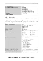
Page 19: ...ly Send cycle if sent periodically 5 s 2 h 10 s Location is determined by input input only valid until the first GPS reception GPS reception Location input using if input selected Town Coordinates Country if input by town is selected Belgium Denmark Germany France Great Britain Italy Liechtenstein Luxembourg Netherlands Austria Switzerland USA Town if input by town is selected 6 towns in Belgium 1...

Page 20: ...9 59 if input by coordinates is selected 46 negative values mean southern latitude Time zone relative to GMT Prefix positive negative Hours 0 13 1 Minutes 0 59 0 Summertime rule Europe USA user defined none All the following times are to be entered as winter time standard time Start of Summer Time on Monday Sunday Date From day for Europe or USA summer time rules Day For user defined summer time r...

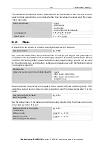
Page 21: ... as the factory settings are always used until the first call setting via objects is ignored Select whether the special rain output is to be used with fixed switching delay This switching output has no delay on rain recognition and 5 minutes delay after it is dry again Set the delay times If the delays are defined using objects then the times set here are only valid up to the first call Send coord...

Page 22: ... Select whether the minimum and maximum value should be used Switching output sends on change on change to rain on change to no rain on change and periodically on change to rain and periodically on change to no rain and periodically Send cycle if sent periodically 5 s 2 h 10 s Object value s with rain 0 1 Use malfunction object No Yes Offset in 0 1 C 50 50 0 Use external reading No Yes Ext Reading...

Page 23: ...um value this value is not retained after a reset Beaufort scale Send pattern never periodically on change on change and periodically at and above change in if sent on change 1 100 20 Send cycle if sent periodically 5 s 2 h Use malfunction object No Yes Measured value additionally output in the Beaufort scale No Yes Send pattern never periodically on change on change and periodically on change of ...

Page 24: ... setting Weather Station P04 KNX GPS Version 01 04 2020 Technical changes and errors excepted 5 Fresh breeze 6 Strong breeze 7 High wind 8 Gale 9 Severe gale 10 Storm 11 Violent storm 12 Hurricane Beaufort Meaning ...

Page 25: ......

Page 26: ...mbH Control and Automation Engineering Sohlengrund 16 75395 Ostelsheim Phone 49 0 70 33 30 945 0 info elsner elektronik de Germany Fax 49 0 70 33 30 945 20 www elsner elektronik de Technical support 49 0 70 33 30 945 250 ...

Reviews: