background image

13

Addressing the equipment

Sensor Sewi KNX TH-L-Pr

 • Version: 17.11.2016 • Technical changes and errors excepted.

3.

Addressing the equipment

The equipment is delivered with the bus address 15.15.250. You can program a differ-
ent address in the ETS by overwriting the address 15.15.250 or by teaching the device
via the programming button. 

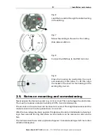
The programming button is on the inside of the housing (Fig. 4: No. 7).

4.

Maintenance

The brightness sensor, the motion sensor and the air slots on the side must not get
dirty or covered. As a rule, it is sufficient to wipe the device with a soft, dry cloth twice
a year.

Summary of Contents for Sewi KNX TH-L-Pr

Page 1: ...Installation and Adjustment Item number 70398 EN Sewi KNXTH L Pr Combined Indoor Sensor...

Page 2: ...tocol 15 5 1 List of all communication objects 15 6 Parameter setting 29 6 1 Behaviour on power failure restoration of power 29 6 2 General settings 30 6 3 Motion detector 30 6 3 1 Master 1 2 3 4 32 6...

Page 3: ...ion 17 11 2016 Technical changes and errors excepted 6 17 Comfort field 65 6 18 Variable comparator 66 6 18 1 Control variable comparator 1 2 3 4 66 6 19 Computer 66 6 19 1 Computer 1 8 67 6 20 Logic...

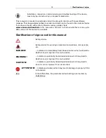
Page 4: ...eshooting of the device must only be carried out by a competent electrician Safety advice Safety advice for working on electrical connections components etc DANGER indicates an immediately hazardous s...

Page 5: ...4 Clarification of signs...

Page 6: ...t value and external value can be set as a percentage Bus message whether the values for temperature and air humidity are within the comfort field DIN 1946 Dew point calculation Switching outputs for...

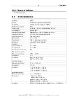
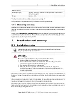
Page 7: ...tage KNX bus voltage Bus current max 10 mA Data output KNX bus plug in terminal BCU type Integrated microcontroller PEI type 0 Group addresses max 2000 Assignments max 2000 Communication objects 377 T...

Page 8: ...ted live components inside the device National legal regulations are to be followed Ensure that all lines to be assembled are free of voltage and take precautions against accidental switching on Do no...

Page 9: ...lease ensure that the measurement results of temperature and humidity are affected as little as possible by external influences Possible sources of interference include Direct sunlight Drafts from win...

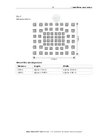
Page 10: ...or Sewi KNX TH L Pr Version 17 11 2016 Technical changes and errors excepted Size of the coverage area Distance Length Width 2 50 m approx 7 42 m approx 5 66 m 3 50 m approx 10 38 m approx 7 92 m Fig...

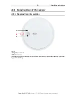
Page 11: ...7 11 2016 Technical changes and errors excepted 2 3 Construction of the sensor 2 3 1 Housing from the outside 1 Fig 3 1 Brightness sensor 2 Motion sensor A Recess to open the housing When closing the...

Page 12: ...ly Fig 4 1 Brightness sensor 2 Motion sensor 3 Sensors for temperature humidity 4 a b Long holes for mounting hole distance 60 mm 5 KNX terminal BUS 6 Programming LED 7 Programming button 8 Cable bush...

Page 13: ...After the bus voltage has been applied the device will enter an initialisation phase last ing a few seconds During this phase no information can be received or sent via the bus The motion sensor has...

Page 14: ...u can program a differ ent address in the ETS by overwriting the address 15 15 250 or by teaching the device via the programming button The programming button is on the inside of the housing Fig 4 No...

Page 15: ...14 Maintenance Sensor Sewi KNX TH L Pr Version 17 11 2016 Technical changes and errors excepted...

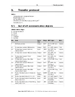
Page 16: ...ature sensor Measured value Output R CT 9 1 DPT_Val ue_Temp 2 bytes 44 Temperature sensor Total measurement Output R CT 9 1 DPT_Val ue_Temp 2 bytes 45 Temperature sensor Min Max measurement query Inpu...

Page 17: ...old value 3 Switching delay from 0 to 1 Input WC 7 5 DPT_Time PeriodSec 2 bytes 68 Temp threshold value 3 Switching delay from 1 to 0 Input WC 7 5 DPT_Time PeriodSec 2 bytes 69 Temp threshold value 3...

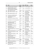
Page 18: ...ss sensor 2 threshold value 2 Switching output Output R CT 1 1 DPT_Switch 1 bit 141 Brightness sensor 2 threshold value 2 Switching output block Input WC 1 1 DPT_Switch 1 bit 143 Brightness sensor 2 t...

Page 19: ...Minimum measurement Output R CT 9 7 DPT_Val ue_Humidity 2 bytes 319 Humidity sensor Maximum measurement Output R CT 9 7 DPT_Val ue_Humidity 2 bytes 320 Humidity sensor Min Max measurement reset Input...

Page 20: ...eshold value 4 1 0 Input WC 1 1 DPT_Switch 1 bit 351 Humidity threshold value 4 Delay from 0 to 1 Input WC 7 5 DPT_Time PeriodSec 2 bytes 352 Humidity threshold value 4 Delay from 1 to 0 Input WC 7 5...

Page 21: ...itch 1 bit 487 Temp controller Setpoint comfort heating Input Output RWCT 9 1 DPT_Val ue_Temp 2 bytes 488 Temp controller Setpoint comfort heating 1 0 Input WC 1 1 DPT_Switch 1 bit 489 Temp controller...

Page 22: ...1 DPT_Switch 1 bit 508 Temp controller Status cooling level 2 1 ON 0 OFF Output R CT 1 1 DPT_Switch 1 bit 509 Temp controller Comfort extension status Input Output RWCT 1 1 DPT_Switch 1 bit 510 Temp c...

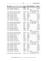
Page 23: ...Output Output R CT 5 1 DPT_Scaling 1 byte 1117 Control variable comparator 1 Block block Output WC 1 2 DPT_Bool 1 bit 1118 Control variable comparator 2 Input 1 Input WC 5 1 DPT_Scaling 1 byte 1119 C...

Page 24: ...41 Computer 1 Input I1 Input RWCT 4 bytes 1142 Computer 1 Input I2 Input RWCT 4 bytes 1143 Computer 1 Input I3 Input RWCT 4 bytes 1144 Computer 1 Output O1 Output R CT 4 bytes 1145 Computer 1 Output O...

Page 25: ...mputer 5 Output O1 Output R CT 4 bytes 1177 Computer 5 Output O2 Output R CT 4 bytes 1178 Computer 5 Condition text Output R CT 16 0 DPT_String_ASCII 14 bytes 1179 Computer 5 Monitoring status Output...

Page 26: ...2 DPT_Bool 1 bit 1400 Logic input 10 Input WC 1 2 DPT_Bool 1 bit 1401 Logic input 11 Input WC 1 2 DPT_Bool 1 bit 1402 Logic input 12 Input WC 1 2 DPT_Bool 1 bit 1403 Logic input 13 Input WC 1 2 DPT_B...

Page 27: ...1 1 DPT_Switch 1 bit 1443 OR logic 1 1 bit switching output Output R CT 1 2 DPT_Bool 1 bit 1444 OR logic 1 8 bit output A Output R CT 1 byte 1445 OR logic 1 8 bit output B Output R CT 1 byte 1446 OR l...

Page 28: ...r 1 Brightness threshold value on Input Output RWCT 9 4 DPT_Val ue_Lux 2 bytes 1532 Motion detector Master 1 Brightness threshold value off Input Output RWCT 9 4 DPT_Val ue_Lux 2 bytes 1533 Motion det...

Page 29: ...4 bytes 1555 Motion detector Master 3 Switch on delay Input LSK 7 5 DPT_Time PeriodSec 2 bytes 1556 Motion detector Master 3 Switch off delay Input LSK 7 5 DPT_Time PeriodSec 2 bytes 1557 Motion detec...

Page 30: ...DPT_Scaling 1 byte 1586 Light controller Target actual difference Input Output RWCT 9 4 DPT_Val ue_Lux 2 bytes 1587 Light controller Reset time Input Output RWCT 7 5 DPT_Time PeriodSec 2 bytes 1588 Li...

Page 31: ...nd after a reset it takes 15 seconds until the sensor is ready for operation Activate the test object if you would like to test the motion detection while commis sioning With an active test object you...

Page 32: ...set can be found in chapter Align communication between master and slave page 35 Set the sending cycle shorter than the master s switch off delay Set the object type and value for the cycle reset inpu...

Page 33: ...detection can be used via separate threshold values for switch on and switch off or dependent on daylight The separate threshold values are ideal for controlling the light in rooms which are only illu...

Page 34: ...the measured bright ness value If the room brightness later exceeds this total value because the room is illuminated by daylight the motion control is switched off Settings for all types of motion det...

Page 35: ...io call up 2 byte counter without math symbol 2 byte counter with math symbol 2 byte floating point 4 byte counter without math symbol 4 byte counter with math symbol 4 byte floating point Output valu...

Page 36: ...r than the master s switch off delay Thereby it is ensured that the master does not perform a switch off action while the slave is still de tecting a motion Slave cycle reset The cycle reset for the s...

Page 37: ...TH L Pr detects the brightness in the room Activate the light control Set in which cases the data received via object for setpoint value setpoint value ac tual difference dimming increment and times...

Page 38: ...output This results in the manual light operation having priority Regulation starts on movement reception of a start stop object reception of a start stop object or movement Regulation stops on moveme...

Page 39: ...external value Set the mixed value calculation if desired If an external portion is used all of the following settings threshold values etc are related to the overall reading Use interruptions No Yes...

Page 40: ...be used for the initial start up as the factory settings are always used until the first communication setting via objects is ignored Set the threshold value directly in the application program using...

Page 41: ...ype of threshold value specification Switching output Set the behaviour of the switching output when a threshold value is exceeded under cut The output switching delay can be set using objects or dire...

Page 42: ...2 h Use switching output block No Yes Analysis of the blocking object At value 1 block At value 0 release At value 0 block At value 1 release Blocking object value before 1st communication 0 1 Behavio...

Page 43: ...ge of mode may be triggered manually or automatically e g by a timer window contact The mode may be switched with two 8 bit objects of different priority Objects HVAC mode Prio 2 for switching in ever...

Page 44: ...etpoint values You may enter separate setpoint values for each mode or use the comfort setpoint as a basic value Mode after reset Comfort Standby Eco Building protection Behaviour of the blocking obje...

Page 45: ...en having guests The duration of this comfort extensi on period is set After the comfort extension period expires the system returns to eco mode Comfort Setpoint Comfort mode is usually used for dayti...

Page 46: ...a basis If the comfort setpoint value is used as a basis the reduction increment of the value is set Eco setpoint Eco mode is usually used for night mode If setpoint values are entered separately A s...

Page 47: ...you can decide whether to use a common control variable for heating and cooling If the 2nd level has a common control variable you also determine the control mode of the 2nd level here Starting heati...

Page 48: ...which the maximum control variable value is reached i e the point at which maximum heating power is activated The reset time shows how quickly the controller responds to deviations from the set point...

Page 49: ...common control variable for heating and cooling 0 is always transmitted as a fixed value 2 point control only level 2 2 point control is used for systems which are only set to ON or OFF When blocked...

Page 50: ...tered or predetermined applications can be selected In the 2nd level therefore only for 2 level cooling cooling is controlled via a PI or a 2 point control In level 2 the setpoint deviation between th...

Page 51: ...ntrol variable for heating and cooling 0 is always transmitted as a fixed value PI control with predetermined application This setting provides fixed parameters for a cooling ceiling Now specify what...

Page 52: ...he objective is to prevent a too great a difference between indoor and outdoor temperature in order to keep the energy consumption low Activate the summer compensation Using the points 1 and 2 define...

Page 53: ...llation for the sensor below point 1 the target value is in 0 1 C 0 500 200 above point 2 the target value is in 0 1 C 0 500 260 Send pattern periodically on change on change and periodically on chang...

Page 54: ...Threshold value Set in which cases threshold values and delay times received are to be kept per object The parameter is only taken into consideration if the specification setting by object is activate...

Page 55: ...until first call 1000 150000 60000 Object value limit min in Lux 1000 150000 Object value limit max in Lux 1000 150000 Type of threshold change Absolute value Increase decrease Increment in Lux upon...

Page 56: ...red Use switching output block No Yes Analysis of the blocking object At value 1 block At value 0 release At value 0 block At value 1 release Blocking object value before first call 0 1 Action when lo...

Page 57: ...s threshold values etc are related to the overall reading Night is recognised below Lux 1 1000 10 Hysteresis in Lux 0 500 5 Delays can be set via objects in seconds No Yes Switching delay on night non...

Page 58: ...et the threshold value directly in the application program using parameters or define them via the bus using a communication object Threshold value setting using parameter Set the threshold values and...

Page 59: ...t value limit min in 0 1 RH 1 1000 Object value limit max in 0 1 RH 1 1000 Type of threshold value change Absolute value Increase decrease Increment upon increase decrease change 0 1 RH 2 0 RH 20 0 RH...

Page 60: ...lysis of the blocking object At value 1 block At value 0 release At value 0 block At value 1 release Blocking object value before first communi cation 0 1 Behaviour of the switching output On block Do...

Page 61: ...lid until the first communication of a new setpoint value For units which have already been ta ken into service the last communicated setpoint value can be used Basically an air humidity range is spec...

Page 62: ...ence between the two levels must be defined i e the setpoint value which when exceeded triggers the switch to the 2nd level Determine the deviation from the setpoint value at which the maximum variabl...

Page 63: ...rature of the coolant which is based on the current dewpoint temperature offset deviation The switching output of the coolant temperature monitoring system can provide a warning prior to any build up...

Page 64: ...eceived via communication object never after power supply restoration after power supply restoration and programming Start offset in C valid until first communication 0 200 30 Increment for offset cha...

Page 65: ...periodically Send cycle is only sent if periodically is selected 5 s 10 s 30 s 2 h Use switching output block No Yes Analysis of the blocking object At value 1 block At value 0 release At value 0 bloc...

Page 66: ...eresis 1 C Use absolute humidity No Yes Sending pattern never periodically on change on change and periodically At and above change of if sent on change 0 1 g 0 2 g 0 5 g 1 0 g 2 0 g 5 0 g Send cycle...

Page 67: ...menus for the further setting of the computer are then displayed Use comparator 1 2 3 4 No Yes Output delivers Maximum value Minimum value Average value Use input 1 2 3 4 5 No Yes Output sends on cha...

Page 68: ...supply restoration and programming Function I Input Prerequisite E1 E2 Prerequisite E1 E2 Prerequisite E1 E2 Prerequisite E1 E2 Prerequisite E1 E2 Prerequisite E1 E2 E3 Prerequisite E2 E1 E3 Prerequis...

Page 69: ...t range depending on the type of output if the condition is not met 0 Input range depending on the type of output if the monitoring time period is exceeded 0 Input range depending on the type of outpu...

Page 70: ...nitoring status should have if the monitoring period is exceeded without feedback Output value if applicable A1 A2 if the monitoring time period is exceeded 0 Input range depending on the type of outp...

Page 71: ...tions are available for AND and OR logic Monitoring period 5 s 2 h 1 min Value of the object monitoring status if period is exceeded 0 1 Use block No Yes Analysis of the blocking object At value 1 blo...

Page 72: ...the AND OR logic Output type a 1 Bit object two 8 bit objects Output value if logic 1 1 0 Output value if logic 0 1 0 Output value If block is active 1 0 Output value if monitoring period is exceeded...

Page 73: ...hange of logic and periodically on change of logic to 1 and periodically on change of logic to 0 and periodically on change of logic object receipt on change of logic object receipt and periodically S...

Page 74: ...ic input 12 inverted Logic input 13 Logic input 13 inverted Logic input 14 Logic input 14 inverted Logic input 15 Logic input 15 inverted Logic input 16 Logic input 16 inverted Temperature sensor malf...

Page 75: ...re controller inactive Eco temperature controller active Eco temperature controller inactive Frost protection temperature controller active Frost protection temperature controller inactive Heating 1 t...

Page 76: ...to those of the AND logic In addition the following inputs are available for the OR logic Switching output AND logic 1 Switching output AND logic 1 inverted Switching output AND logic 2 Switching outp...

Page 77: ...GmbH Control and AutomationTechnology Sohlengrund 16 75395 Ostelsheim Phone 49 0 7033 30945 0 info elsner elektronik de Germany Fax 49 0 7033 30945 20 www elsner elektronik de Technical support 49 0...

Reviews: