background image

51

Parameter setting

Sensor Vari KNX 3L-TH-D

 • Status: 19.10.2016 • Errors excepted. Subject to technical changes.

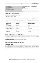
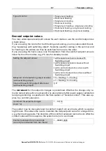
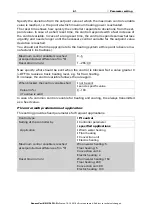
Specify the 

sending pattern

, a 

Text

for comfortable and uncomfortable and the ma-

gnitude of the 

Object value

.

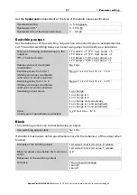
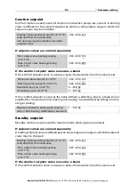
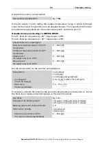
Define the comfort field by specifying the minimum and maximum values for tempe-
rature and humidity. The specified standard values comply with DIN 1946

Temperature hysteresis: 1°C
Relative humidity hysteresis: 2% RH
Absolute humidity hysteresis: 2 g/kg

6.13. Air pressure measurement

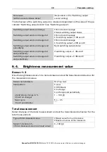
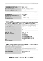
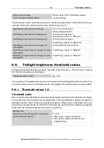
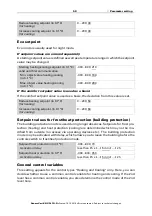
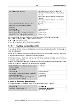
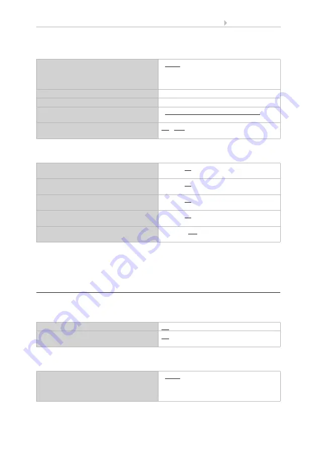
If necessary, activate the air pressure malfunction object. Specify whether the measu-
red value is, in addition, to be outputted as barometric pressure (see below 

Information

on air pressure

).

Define the send pattern and, if necessary, activate the minimum and maximum value
(these values are not retained after a reset). 

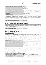
Sending pattern

• never
• periodically
• on change
• on change and periodically

  Text for comfortable

[Free text max. 14 chars.]

  Text for uncomfortable

[Free text max. 14 chars.]

Object value is at

• comfortable = 1 | uncomfortable = 0
• comfortable = 0 | uncomfortable = 1

Send cycle 

(if sent periodically)

5 s • 10 s • 30 s… • 2 h

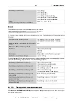
Maximum temperature in °C 
(Standard 26°C)

25 ... 40; 26

Minimum temperature in °C
(Standard 20°C)

10 ... 21; 20

Maximum relative humidity in %

(

Standard 65%)

52 ... 90; 65

Minimum relative humidity in %
(Standard 30%)

10 ... 43; 30

Maximum absolute humidity in 0.1 g/kg
(Standard 115 g/kg)

50 ... 200; 115

Use malfunction object

No • Yes

Measured value additionally 
output as barometric pressure

No • Yes

Send pattern measurement

• never
• periodically
• on change
• on change and periodically

Summary of Contents for Vari KNX 3L-TH-D

Page 1: ...rol and AutomationTechnology Sohlengrund 16 75395 Ostelsheim Phone 49 0 70 33 30 945 0 info elsner elektronik de Germany Fax 49 0 70 33 30 945 20 www elsner elektronik de Vari KNX 3L TH D Combined Sensor for Outdoor or Indoor Application Technical support 49 0 70 33 30 945 250 ...

Page 2: ...ing 34 6 1 Behaviour on power failure restoration of power 34 6 1 1 Storage of threshold values 34 6 1 2 Malfunction objects 34 6 1 3 General settings 34 6 2 Temperature Measurement 35 6 3 Temperature threshold values 35 6 3 1 Threshold values 1 4 36 6 4 Brightness measurement value 38 6 5 Brightness threshold values sensor 1 3 and total brightness threshold values 39 6 5 1 Threshold values 1 4 39...

Page 3: ...d errors excepted 6 15 2 Cooling control level 1 2 62 6 16 Summer Compensation 64 6 17 Humidity PI control 66 6 18 Variable comparator 68 6 18 1 Control variable comparator 1 2 3 4 68 6 19 Computer 69 6 19 1 Computers 1 8 69 6 20 Logic 73 6 20 1 AND logic 1 8 and OR logic outputs 1 8 73 6 20 2 AND logic connection inputs 75 6 20 3 Connection inputs of the OR logic 78 ...

Page 4: ...leshooting of the device must only be carried out by a competent electrician Safety advice Safety advice for working on electrical connections components etc DANGER indicates an immediately hazardous situation which will lead to death or severe injuries if it is not avoided WARNING indicates a potentially hazardous situation which may lead to death or severe injuries if it is not avoided CAUTION i...

Page 5: ...4 Clarification of signs ...

Page 6: ... case with Mixed value calculation The share of internal measurement value and external value can be set as a percentage In addition the bus output will indicate whether the values are inside the comfort field DIN 1946 The dewpoint will be calculated Air pressure measurement Output of the value as normal pressure and optionally as barometric pressure Switching outputs for all measured and computed...

Page 7: ...c Colour White Translucent Assembly Surface mount Protection category IP 44 Dimensions approx 65 80 30 W H D mm Weight approx 60 g Ambient temperature Operation 25 80 C Storage 40 85 C avoid condensation Operating voltage KNX bus voltage Bus current max 20 mA Data output KNX bus connector terminal BCU type Integrated microcontroller PEI type 0 Group addresses max 2000 Assignments max 2000 Communic...

Page 8: ...uaranteed The device is only to be used for its intended purpose Any improper modification or failure to follow the operating instructions voids any and all warranty and guarantee claims After unpacking the device check it immediately for possible mechanical damage If it has been damaged in transport inform the supplier immediately The device may only be used as a fixed site installation that mean...

Page 9: ... should not be shaded by structures or for example trees Ensure no shadow is thrown on the device by an extended awning Temperature measurements can also be distorted by external influences such as warming or cooling of the building structure on which the sensor is mounted sunlight heating or cold water pipes Temperature variations from such sources of interference Fig 1 The device must be attache...

Page 10: ...he device if water e g rain can get into it 3 Fig 4 1 Position of the brightness sen sors 1 3 With alignment of the device to the south Sensor 1 East Sensor 2 South Sensor 3 West 2 Semi transparent cover pressure sensor below 3 Position of the Signal LED un der the cover LED is freely con trolled via two objects 4 Position of the programming LED under the cover 5 Lower part of housing 6 Temperatur...

Page 11: ...g for wall or pole installation Wall installation Use fixing materials dowels screws that are suitable for the base Fig 5 The cover and lower part of the housing are connected together Pull both parts apart in a straight line Fig 6 The device is installed with two screws Break off the two longitudinal holes in the housing Longitudinal holes Fig 7 a b a If the power lead is to be hidden when in sta...

Page 12: ...ncluded ex works and this can be used as a template b If the power lead is to be surface mount ed the cable guide is broken off The lead is then fed into the device from the bot tom of the housing Cable guide Fig 8 Feed the power lead through the rubber gas ket Rubber gasket Fig 9 Dimensions in mm Varia tions are possible for tech nical reasons A B2 longitudinal holes 8 mm 5 mm C Position of the c...

Page 13: ...the enclosed stainless steel mounting band 2 4 3 Connection The connector is in the lower part of the housing Fig 10 Feed the mounting band through the eyelets in the lower part of the housing Fig 11 Break the cable guide off Feed the power lead through the rubber gas ket Rubber gasket Cable guide Fig 12 Connect the device to the KNX bus via the pluggable terminal KNX ...

Page 14: ...5 250 or by teaching the device via the programming button The programming button can be reached through the opening on the underside of the housing it is recessed by approx 8 mm Use a thin object to reach the button e g a 1 5 mm wire Fig 13 Put the cover on the lower part This also makes the plug in connection between the board in the cover and the socket in the lower part Fig 14 a b 1 Programmin...

Page 15: ...the system to start up and pose a danger to humans Always disconnect the system from the mains power before maintenance or cleaning The device should be regularly checked twice a year for soiling and cleaned if required If there is major soiling the function of the sensor may be compromised ATTENTION The device may be damaged if water penetrates the housing Do not clean with high pressure cleaners...

Page 16: ...witch 1 bit 41 Temperature sensor Malfunction Output R CT 1 1 DPT_Switch 1 bit 42 Temperature sensor External measurement Input WCT 9 1 DPT_Val ue_Temp 2 bytes 43 Temperature sensor Measured value Output R CT 9 1 DPT_Val ue_Temp 2 bytes 44 Temperature sensor Total measurement Output R CT 9 1 DPT_Val ue_Temp 2 bytes 45 Temperature sensor Min Max measurement query Input WC 1 017 DPT_Trig ger 1 bit 4...

Page 17: ...d value 2 Switching output block Input WC 1 1 DPT_Switch 1 bit 65 Temp threshold value 3 Absolute value Input Output RWCT 9 1 DPT_Val ue_Temp 2 bytes 66 Temp threshold value 3 1 0 Input WC 1 1 DPT_Switch 1 bit 67 Temp threshold value 3 Switching delay from 0 to 1 Input WC 7 5 DPT_Time PeriodSec 2 bytes 68 Temp threshold value 3 Switching delay from 1 to 0 Input WC 7 5 DPT_Time PeriodSec 2 bytes 69...

Page 18: ... Switching output block Input WC 1 1 DPT_Switch 1 bit 108 Brightness sensor 1 threshold value 2 Absolute value Input Output RWCT 9 4 DPT_Val ue_Lux 2 bytes 109 Brightness sensor 1 threshold value 2 1 0 Input WC 1 1 DPT_Switch 1 bit 110 Brightness sensor 1 threshold value 2 Delay from 0 to 1 Input WC 7 5 DPT_Time PeriodSec 2 bytes 111 Brightness sensor 1 threshold value 2 Delay from 1 to 0 Input WC...

Page 19: ...ness sensor 2 threshold value 1 Delay from 0 to 1 Input WC 7 5 DPT_Time PeriodSec 2 bytes 132 Brightness sensor 2 threshold value 1 Delay from 1 to 0 Input WC 7 5 DPT_Time PeriodSec 2 bytes 133 Brightness sensor 2 threshold value 1 Switching output Output R CT 1 1 DPT_Switch 1 bit 134 Brightness sensor 2 threshold value 1 Switching output block Input WC 1 1 DPT_Switch 1 bit 136 Brightness sensor 2...

Page 20: ...155 Brightness sensor 2 threshold value 4 Switching output block Input WC 1 1 DPT_Switch 1 bit 157 Brightness sensor 3 threshold value 1 Absolute value Input Output RWCT 9 4 DPT_Val ue_Lux 2 bytes 158 Brightness sensor 3 threshold value 1 1 0 Input WC 1 1 DPT_Switch 1 bit 159 Brightness sensor 3 threshold value 1 Delay from 0 to 1 Input WC 7 5 DPT_Time PeriodSec 2 bytes 160 Brightness sensor 3 thr...

Page 21: ...t 180 Brightness sensor 3 threshold value 4 Delay from 0 to 1 Input WC 7 5 DPT_Time PeriodSec 2 bytes 181 Brightness sensor 3 threshold value 4 Delay from 1 to 0 Input WC 7 5 DPT_Time PeriodSec 2 bytes 182 Brightness sensor 3 threshold value 4 Switching output Output R CT 1 1 DPT_Switch 1 bit 183 Brightness sensor 3 threshold value 4 Switching output block Input WC 1 1 DPT_Switch 1 bit 185 Total b...

Page 22: ...it 204 Total brightness threshold value 3 Switching output block Input WC 1 1 DPT_Switch 1 bit 206 Total brightness threshold value 4 Absolute value Input Output RWCT 9 4 DPT_Val ue_Lux 2 bytes 207 Total brightness threshold value 4 1 0 Input WC 1 1 DPT_Switch 1 bit 208 Total brightness threshold value 4 Delay from 0 to 1 Input WC 7 5 DPT_Time PeriodSec 2 bytes 209 Total brightness threshold value...

Page 23: ...ss threshold 3 delay from 0 to 1 Input WC 7 5 DPT_Time PeriodSec 2 bytes 230 Twilight brightness threshold 3 delay from 1 to 0 Input WC 7 5 DPT_Time PeriodSec 2 bytes 231 Twilight brightness threshold value 3 Switching output Output R CT 1 1 DPT_Switch 1 bit 232 Twilight brightness threshold value 3 Switching output block Input WC 1 1 DPT_Switch 1 bit 234 Twilight brightness threshold value 4 Abso...

Page 24: ...threshold value 1 Delay from 0 to 1 Input WC 7 5 DPT_Time PeriodSec 2 bytes 334 Humidity threshold value 1 Delay from 1 to 0 Input WC 7 5 DPT_Time PeriodSec 2 bytes 335 Humidity threshold value 1 Switching output Output R CT 1 1 DPT_Switch 1 bit 336 Humidity threshold value 1 Switching output block Input WC 1 1 DPT_Switch 1 bit 337 Humidity threshold value 2 Absolute value Input Output RWCT 9 7 DP...

Page 25: ...ock Input WC 1 1 DPT_Switch 1 bit 381 Dewpoint Measured value Output R CT 9 1 DPT_Val ue_Temp 2 bytes 382 Coolant temp Threshold value Output R CT 9 1 DPT_Val ue_Temp 2 bytes 383 Coolant temp Actual value Input RWCT 9 1 DPT_Val ue_Temp 2 bytes 384 Coolant temp Offset change 1 0 Input WC 1 1 DPT_Switch 1 bit 385 Coolant temp Current offset Output R CT 9 1 DPT_Val ue_Temp 2 bytes 386 Coolant temp Sw...

Page 26: ...Trig ger 1 bit 410 Air pressure sensor Pressure range text Output R CT 16 0 DPT_String_ASCII 14 bytes 411 Air pressure threshold value 1 Absolute value Input Output RWCT 14 58 DPT_Val ue_Pressure 4 bytes 412 Air pressure threshold value 1 1 0 Input WC 1 1 DPT_Switch 1 bit 413 Air pressure threshold value 1 Delay from 0 to 1 Input WC 7 5 DPT_Time PeriodSec 2 bytes 414 Air pressure threshold value 1...

Page 27: ...Input WC 1 1 DPT_Switch 1 bit 431 Air pressure threshold value 4 Delay from 0 to 1 Input WC 7 5 DPT_Time PeriodSec 2 bytes 432 Air pressure threshold value 4 Delay from 1 to 0 Input WC 7 5 DPT_Time PeriodSec 2 bytes 433 Air pressure threshold value 4 Switching output Output R CT 1 1 DPT_Switch 1 bit 434 Air pressure threshold value 4 Switching output block Input WC 1 1 DPT_Switch 1 bit 481 Temp co...

Page 28: ...t 498 Temp controller Setpoint eco cooling Input Output RWCT 9 1 DPT_Val ue_Temp 2 bytes 499 Temp controller Setpoint eco cooling 1 0 Input WC 1 1 DPT_Switch 1 bit 500 Temp controller Heating control variable 1 level Output R CT 5 1 DPT_Scaling 1 byte 501 Temp controller Heating control variable 2nd level Output R CT 5 1 DPT_Scaling 1 byte 502 Temp controller Control variable cooling 1st level Out...

Page 29: ...dity controller Control variable dehumidification of the 2nd level Output R CT 5 1 DPT_Scaling 1 byte 526 Humidity controller Control variable humidification Output R CT 5 1 DPT_Scaling 1 byte 527 Humidity controller Dehumidification status 1 ON 0 OFF Output R CT 1 1 DPT_Switch 1 bit 528 Humidity controller Dehumidification 2 status 1 ON 0 OFF Output R CT 1 1 DPT_Switch 1 bit 529 Humidity controll...

Page 30: ... 5 1 DPT_Scaling 1 byte 1126 Control variable Comparator 3 Input 2 Input WC 5 1 DPT_Scaling 1 byte 1127 Control variable Comparator 3 Input 3 Input WC 5 1 DPT_Scaling 1 byte 1128 Control variable Comparator 3 Input 4 Input WC 5 1 DPT_Scaling 1 byte 1129 Control variable Comparator 3 Input 5 Input WC 5 1 DPT_Scaling 1 byte 1130 Control variable Comparator 3 Output Output R CT 5 1 DPT_Scaling 1 byte...

Page 31: ...DPT_String_ASCII 14 bytes 1155 Computer 2 Monitoring status Output R CT 1 1 DPT_Switch 1 bit 1156 Computer 2 Block 1 block Input WC 1 1 DPT_Switch 1 bit 1157 Computer 3 Input I1 Input RWCT 4 bytes 1158 Computer 3 Input I2 Input RWCT 4 bytes 1159 Computer 3 Input I3 Input RWCT 4 bytes 1160 Computer 3 Output O1 Output R CT 4 bytes 1161 Computer 3 Output O2 Output R CT 4 bytes 1162 Computer 3 Conditi...

Page 32: ... 1 DPT_Switch 1 bit 1189 Computer 7 Input I1 Input RWCT 4 bytes 1190 Computer 7 Input I2 Input RWCT 4 bytes 1191 Computer 7 Input I3 Input RWCT 4 bytes 1192 Computer 7 Output O1 Output R CT 4 bytes 1193 Computer 7 Output O2 Output R CT 4 bytes 1194 Computer 7 Condition text Output R CT 16 0 DPT_String_ASCII 14 bytes 1195 Computer 7 Monitoring status Output R CT 1 1 DPT_Switch 1 bit 1196 Computer 7...

Page 33: ...t output B Output R CT 1 byte 1418 AND logic 2 Block Input WC 1 1 DPT_Switch 1 bit 1419 AND logic 3 1 bit switching output Output R CT 1 2 DPT_Bool 1 bit 1420 AND logic 3 8 bit output A Output R CT 1 byte 1421 AND logic 3 8 bit output B Output R CT 1 byte 1422 AND logic 3 Block Input WC 1 1 DPT_Switch 1 bit 1423 AND logic 4 1 bit switching output Output R CT 1 2 DPT_Bool 1 bit 1424 AND logic 4 8 b...

Page 34: ...ut WC 1 1 DPT_Switch 1 bit 1455 OR logic 4 1 bit switching output Output R CT 1 2 DPT_Bool 1 bit 1456 OR logic 4 8 bit output A Output R CT 1 byte 1457 OR logic 4 8 bit output B Output R CT 1 byte 1458 OR logic 4 Block Input WC 1 1 DPT_Switch 1 bit 1459 OR logic 5 1 bit switching output Output R CT 1 2 DPT_Bool 1 bit 1460 OR logic 5 8 bit output A Output R CT 1 byte 1461 OR logic 5 8 bit output B ...

Page 35: ...is a threshold value once set per parameter or via a communication object is retained until a new threshold value is sent via a communication object The last th reshold value set by communication object is saved in the device so that it is retained during a power outage and is available once again when power is restored 6 1 2 Malfunction objects Malfunction objects are sent after every reset and a...

Page 36: ...m readings can be saved and sent to the bus Use the Reset temperature min max value objects to reset the values to the current readings The values are not retained after a reset 6 3 Temperature threshold values Activate the required temperature threshold values The menus for setting of the th reshold values are displayed Function of the signal LED always OFF flashes if a signal LED object receives...

Page 37: ...se During initial commissioning a threshold value must be defined which will be valid until the first communication with a new threshold value For units which have already been taken into service the last communicated threshold value can be used Basically a temperature range is given in which the threshold value can be changed object value limit A set threshold value will be retained until a new v...

Page 38: ...hold value TV above 1 TV hyst below 0 TV above 0 TV hyst below 1 TV below 1 TV hyst above 0 TV below 0 TV hyst above 1 Delays can be set via objects in seconds No Yes Switching delay from 0 to 1 If delay can be set via objects valid until 1st communication None 1 s 2 s 5 s 10 s 2 h Switching delay from 1 to 0 If delay can be set via objects valid until 1st communication None 1 s 2 s 5 s 10 s 2 h S...

Page 39: ...n change Do not send message Send switching output status Switching output sends on change to 1 Do not send message if switching output 1 send 1 Switching output sends on change to 0 Do not send message if switching output 0 send 0 Switching output sends on change and periodically Send switching output status Switching output sends on change to 1 and periodically if switching output 1 send 1 Switc...

Page 40: ...as the factory settings are always used until the first call setting via objects is ignored Select whether the threshold value is to be specified per parameter or via a communi cation object When the threshold value per parameter is specified then the value is set When the threshold value per communication object is specified the starting value object value limit and type of change to the threshol...

Page 41: ...ease change 1000 2000 5000 10000 20000 Hysteresis setting in absolute Hysteresis in of the threshold value for setting in 0 100 50 Hysteresis in Lux for absolute setting 0 150000 30000 When the following conditions apply the output is LV Threshold value GW above 1 GW Hyst below 0 GW above 0 GW Hyst below 1 GW below 1 GW Hyst above 0 GW below 0 GW Hyst above 1 Delays can be set via objects in secon...

Page 42: ...vated further down Please note that the setting After power restoration and pro gramming should not be used for the initial start up as the factory settings are always used until the first call setting via objects is ignored Action upon release with 2 seconds release delay Dependent on the Switching output sends setting Switching output sends on change do not send message Status object s send s Sw...

Page 43: ...er Communications object Threshold value in kLux 1 1000 10 Start threshold value in Lux valid until first call 1 1000 10 Object value limit min in Lux 1 1000 Object value limit max in Lux 1 1000 Type of threshold change Absolute value Increase decrease Increment in Lux upon increase decrease change 1000 2000 5000 10000 20000 Hysteresis setting in absolute Hysteresis in of the threshold value for s...

Page 44: ...gs are always used until the first call setting via objects is ignored Use switching output block No Yes Analysis of the blocking object At value 1 block At value 0 release At value 0 block At value 1 release Blocking object value before first call 0 1 Action when locking do not send message send 0 send 1 Action upon release with 2 seconds release delay Dependent on the Switching output sends sett...

Page 45: ... an external portion is used all of the following settings threshold values etc are related to the overall reading delays received via communication objects never after power supply restoration after power supply restoration and programming Night is recognised below Lux 1 1000 10 Hysteresis in Lux 0 500 5 Delays can be set via objects in seconds No Yes Switching delay on night none 1 s 2 h Switchi...

Page 46: ... gramming should not be used for the initial start up as the factory settings are always used until the first communication setting via objects is ignored Set the threshold value directly in the application program using parameters or define them via the bus using a communication object Threshold value setting using parameters Set the threshold values and hysteresis directly Sending pattern for in...

Page 47: ...of threshold value specification Switching output Set the behaviour of the switching output when a threshold value is exceeded under cut The output switching delay can be set using objects or directly as a parameter Threshold value setting using Parameter Communication objects Starting threshold value in 0 1 RH valid until first communication 1 1000 650 Object value limit min in 0 1 RH 1 1000 Obje...

Page 48: ... periodically is selected 5 s 10 s 30 s 2 h Use switching output block No Yes Analysis of the blocking object At value 1 block At value 0 release At value 0 block At value 1 release Blocking object value before first communi cation 0 1 Behaviour of the switching output On block Do not send message send 0 send 1 On release with 2 seconds release delay Dependent on the Switching output sends setting...

Page 49: ...ed until the first communication setting via objects is ignored During initial commissioning an offset must be defined which is valid until the first communication of a new offset For units which have already been taken into service the last communicated offset can be used A set offset will be retained until a new value or a change is transferred The current value is saved in EEPROM so that it is ...

Page 50: ...30 s 1 min 2 h When the following conditions apply the output is TV Threshold value TV above 1 TV hyst below 0 TV above 0 TV hyst below 1 TV below 1 TV hyst above 0 TV below 0 TV hyst above 1 Delays can be set via objects in seconds No Yes Switching delay from 0 to 1 for setting via objects valid until 1st communication None 1 s 2 s 5 s 10 s 2 h Switching delay from 1 to 0 for setting via objects ...

Page 51: ... Do not send message send 0 send 1 On release with 2 seconds release delay Dependent on the Switching output sends setting Switching output sends on change Do not send message Send switching output status Switching output sends on change to 1 Do not send message if switching output 1 send 1 Switching output sends on change to 0 Do not send message if switching output 0 send 0 Switching output send...

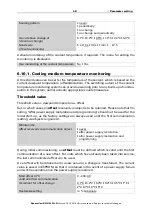
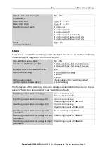
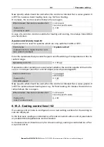
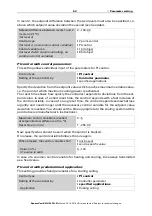
Page 52: ... air pressure Define the send pattern and if necessary activate the minimum and maximum value these values are not retained after a reset Sending pattern never periodically on change on change and periodically Text for comfortable Free text max 14 chars Text for uncomfortable Free text max 14 chars Object value is at comfortable 1 uncomfortable 0 comfortable 0 uncomfortable 1 Send cycle if sent pe...

Page 53: ...the further setting of the threshold values are then displayed 6 14 1 Wind threshold values 1 4 Threshold value Set in which cases threshold values and delay times received are to be kept per object The parameter is only taken into consideration if the specification setting by object is activated further down Please note that the setting After power restoration and pro on change of if sent on chan...

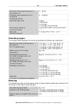
Page 54: ...eded or undercut Set the delay for the switching and in which cases the switch output transmits Maintain the threshold values and delays received via communication object never after power supply restoration after power supply restoration and programming Type of measurement for threshold value calculation Normal air pressure Barometric pressure Threshold value setpoint using Parameter Communicatio...

Page 55: ... if sent periodically 5 s 2 h Use switching output block No Yes Analysis of the blocking object At value 1 block At value 0 release At value 0 block At value 1 release Blocking object value before first call 0 1 Action when locking Do not send message send 0 send 1 Action upon release with 2 seconds release delay Dependent on the Switching output sends setting Switching output sends on change do n...

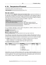
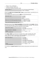
Page 56: ...e temperature control include the setpoint temperatures for the in dividual modes Objects are used to determine which mode is to be selected A change of mode may be triggered manually or automatically e g by a timer window contact The mode may be switched with two 8 bit objects of different priority Objects HVAC mode Prio 2 for switching in everyday operation and HVAC mode Prio 1 for central switc...

Page 57: ...current status of the control variables 0 OFF 0 ON and may for example be used for visualisation or to switch off the heating pump as soon as the heating is switched off Then define the type of control Heating and or cooling may be controlled in two le vels Switch mode via two 8 bit objects HVAC Modes three 1 bit objects Mode after reset Comfort Standby Eco Building protection Behaviour of the blo...

Page 58: ...on The control may be manually reset to comfort mode from eco mode which is used as night mode This allows the user to maintain the daily setpoint value for a longer time e g when having guests The duration of this comfort extension period is set After the comfort extension time expires the system returns to eco mode Type of control Single level heating Dual level heating Single level cooling Dual...

Page 59: ...f setpoint values are entered separately A starting setpoint value is defined as well as a temperature range in which the setpoint value may be changed If the comfort setpoint value is used as a basis If the comfort setpoint value is used as a basis the deviation from this value is set Starting heating cooling setpoint in 0 1 C valid until first communication not upon saving the setpoint value aft...

Page 60: ...ith delay which allows you to leave the building before the controls switch to frost heat protection mode General control variables This setting appears for the control types Heating and Cooling only Here you can decide whether to use a common control variable for heating and cooling If the 2nd level has a common control variable you also determine the control mode of the 2nd level here Reduce hea...

Page 61: ...ich setpoint deviation the second level is added PI control with control parameters This setting allows individual input of the parameters for PI control For heating and cooling separate control variables are used common control variables are used for Level 1 common control variables are used for Level 2 common control variables are used for Level 1 2 Use control variable for 4 6 way valve only fo...

Page 62: ...is blocked Set a value greater 0 OFF to receive a basic heating level e g for floor heating On release the control variable follows the rule again In case of a common control variable for heating and cooling 0 is always transmitted as a fixed value PI control with predetermined application This setting provides fixed parameters for frequent applications Maximum control variable is reached at setpo...

Page 63: ...t should be sent when the control is blocked Set a value greater 0 OFF to receive a basic heating level e g for floor heating On release the control va riable follows the rule again 6 15 2 Cooling control level 1 2 If a cooling control mode is configured one or two setting sections for the cooling le vels are displayed In the first level cooling is controlled by a PI control in which either contro...

Page 64: ...e to the cooling system at this point observe manufacturer s instructions Now specify what should be sent when the control is blocked On release the control variable follows the rule again In case of a common control variable for heating and cooling 0 is always transmitted as a fixed value PI control with predetermined application This setting provides fixed parameters for a cooling ceiling Setpoi...

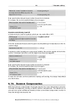
Page 65: ...ntrol variable for heating and cooling 0 is always transmitted as a fixed value 6 16 Summer Compensation With the summer compensation the target value for the room temperature can auto matically be adapted by cooling at higher outdoor temperatures The objective is to prevent a too great a difference between indoor and outdoor temperature in order to keep the energy consumption low Maximum control ...

Page 66: ...ion and set what a 1 or 0 at the block input means and what happens in the event of a block Use summer compensation No Yes Characteristic curve description External temperature point 1 in 0 1 C increments 0 500 200 Outdoor temperature point 2 in 0 1 C increments 0 500 320 below point 1 the target value is in 0 1 C 0 500 200 above point 2 the target value is in 0 1 C 0 500 260 Send pattern periodic...

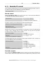
Page 67: ...atus object shows the current status of the output variable 0 OFF 0 ON and can for example be used for visualisation Controller setpoint Set in which cases setpoint values received via object are to be retained Please note that the setting After power supply restoration and programming should not be used Use humidity control No Yes Type of control One level dehumidification Two level dehumidificat...

Page 68: ...nt of a power supply failure and will be available once the power supply is restored In Humidification and dehumidification control mode a dead zone is specified so that no direct changeover switching between humidification and dehumidification is pos sible Humidification starts when the relative air humidity is lower or equal to the setpoint value dead zone value Dehumidification and or humidific...

Page 69: ...deviation is reached You should set the time appropriate for the humidification dehumidification system at this point note manufacturer instructions Now specify what should be sent when the control is blocked On release the control variable follows the rule again 6 18 Variable comparator The integrated variable comparators can output maximum minimum and average values 6 18 1 Control variable compa...

Page 70: ... ignored Output sends on change of output on change of output and periodically when receiving an input object when receiving an input object and periodically Send cycle if sent periodically 5 s 10 s 30 s 5 min 2 h At and above change of if sent on change 1 2 5 10 20 25 50 Analysis of the blocking object at value 1 block at value 0 release at value 0 block at value 1 release Blocking object value b...

Page 71: ...lculation Output 1 E1 X Y Output 2 E2 X Y Transformation General Tolerance for comparison in the case of prerequisite E1 E2 0 4 294 967 295 Input type Selection options depending on the func tion 1 bit 1 byte 0 255 1 byte 0 100 1 byte 0 360 2 byte counter without math symbol 2 byte counter with math symbol 2 byte floating point 4 byte counter without math symbol 4 byte counter with math symbol 4 b...

Page 72: ...range depending on the type of output Output sends on change on change and after reset on change and periodically when receiving an input object when receiving an input object and periodically Type of change is only sent if on change is selected on each change on change to condition met on change to condition not met Send cycle if sent periodically 5 s 2 h 10 s Text if the condition is met Free te...

Page 73: ... or 0 at the block entry means and what happens in the event of a block Output sends on change on change and after reset on change and periodically when receiving an input object when receiving an input object and periodically on change of only if calculations are transmitted for changes 1 Input range depending on the type of input Send cycle if sent periodically 5 s 2 h 10 s Formula for output A1...

Page 74: ...what the out put should send if logic 1 and 0 Value before first call 0 1 Output pattern On block do not send anything send value On release as send pattern see above send current value immediately Use logic inputs Yes No Object value prior to first call for Logic input 1 0 1 Logic input 0 1 Logic input 16 0 1 AND logic 1 not active active AND logic not active active AND logic 8 not active active ...

Page 75: ... 0 255 100 360 127 1 Output value object B if logic 1 0 255 100 360 127 1 Output value object A if logic 0 0 255 100 360 127 0 Output value object B if logic 0 0 255 100 360 127 0 Output value object A if block is active 0 255 100 360 127 0 Output value object B if block is active 0 255 100 360 127 0 Output value object A if monitoring period is exceeded 0 255 100 360 127 0 Output value object B i...

Page 76: ...verted Logic input 3 Logic input 3 inverted Logic input 4 Logic input 4 inverted Logic input 5 Logic input 5 inverted Logic input 6 Logic input 6 inverted Logic input 7 Logic input 7 inverted Logic input 8 Use block No Yes Analysis of the blocking object At value 1 block At value 0 release At value 0 block At value 1 release Blocking object value before first call 0 1 Output pattern On block Do no...

Page 77: ...Temperature Switching output 1 Temperature inverted Switching output 2 Temperature Switching output 2 Temperature inverted Switching output 3 Temperature Switching output 3 Temperature inverted Switching output 4 Temperature Switching output 4 Temperature inverted Switching output 1 Brightness sensor 1 Switching output 1 Brightness sensor 1 inverted Switching output 2 Brightness sensor 1 Switching...

Page 78: ...ing output 1 Twilight Switching output 1 Twilight inverted Switching output 2 Twilight Switching output 2 Twilight inverted Switching output 3 Twilight Switching output 3 Twilight inverted Switching output 4 Twilight Switching output 4 Twilight inverted Switching output 1 Humidity Switching output 1 Humidity inverted Switching output 2 Humidity Switching output 2 Humidity inverted Switching output...

Page 79: ... inactive Humidity controller dehumidification 1 active Humidity controller dehumidification 1 inactive Humidity controller dehumidification 2 active Humidity controller dehumidification 2 inactive Humidity controller humidification active Humidity controller humidification 1 inactive 6 20 3 Connection inputs of the OR logic The OR logic connection inputs correspond to those of the AND logic In ad...

Page 80: ... 60184 white 60185 60189 black WS1 Style PF 60191 60194 white 60196 60199 black WS1000 Style 60201 60204 white 60206 60209 black WS1000 Style PF 60211 60214 white 60216 60219 black Elsner Elektronik GmbH Control and AutomationTechnology Sohlengrund 16 75395 Ostelsheim Phone 49 0 7033 30945 0 info elsner elektronik de Germany Fax 49 0 7033 30945 20 www elsner elektronik de Technical support 49 0 70...

Reviews: