background image

Data Logger  DL210 


Elster-Instromet GmbH  


11 

3.3  Determining an error message 

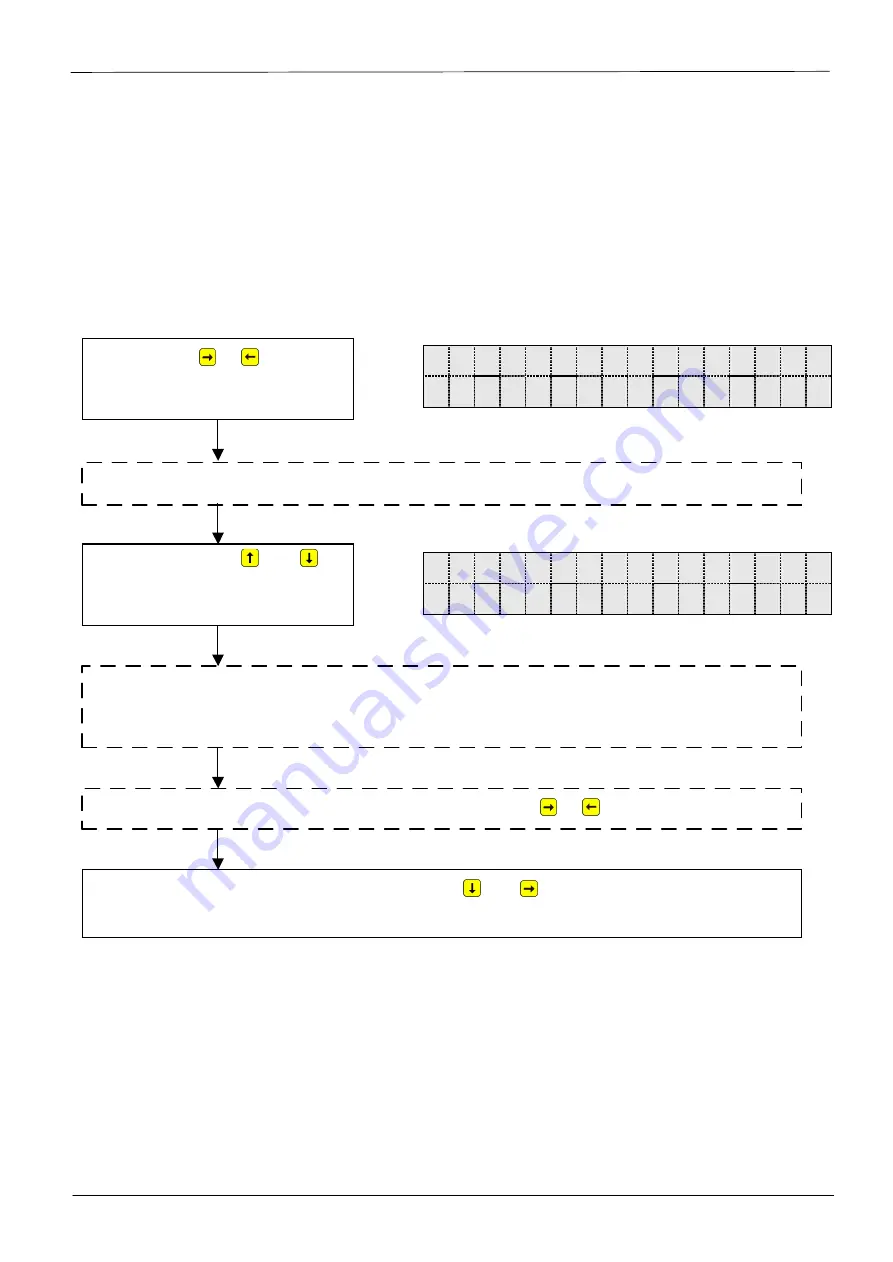
The following describes the procedure of interpreting a message in the display and how it can 
also be cleared. 

The following case serves as an example:  

"

The symbol "W" in the DL210 is on (continuously lit)".

 What should be done ?


          W        S  t  a  t  u  s 


S  .  R  e  g                      6 


The procedure for displaying current messages in the momentary status "Stat" corresponds 
precisely to the above call of messages.


          W        S  R  .  1     


#  6          W  a  r  n  L  i  m  .  I  1 

With the key   or   select the 

list 

Status


(see display on the right) 

The arrow „

“ signifies that a submenu can be called. 

Press the keys   

and


simultaneously

(Skips to entry function) 

Now it can be seen, based on the number and the designation, to the top right which 
message is involved; here: 

Message "6" in the status register SR.1 = Warning limit 

I1 violated

. The corresponding table is listed in Chap. 3. 

If required, further messages can be called with the key   or   . 

With simultaneous depression of the two keys   and   (= "ESC") the submenu is left 
again and you are returned to the Status list. 

Summary of Contents for DL210

Page 1: ...chstbelastungs Anzeigegerät fmax 10 Hz ungeeichte Werte xx xx xxxx DL210 Please note The present short form instructions are used for description of the main functions and are just an abridgement of the complete operating manual 73018816 Attention should be paid to the operational manual DL210 Short Form of the operating manual V1 00 Short Form Instructions 73018818 SW Version V1 00 and above Edit...

Page 2: ...djustable measure ment period or one month Labels F max Maximum highest value within the time range F min Minimum lowest value within the time range F D Change volume within the time range F Æ Mean mean within the time range 2 Archive If an arrow points upwards to the label Archive then the displayed value is an archived value This was frozen at a defined point in time and cannot be changed 3 Devi...

Page 3: ...k The PTB logbook calibration logbook is full Modification of the parameters which are taken into account in the PTB logbook are only possible with the programming lock cali bration lock open refer to 4 o On line A data transfer via the optical or permanently wired interface is running In each case the other interface cannot then be used 4 Menu Here is displayed to which list according to Chapter ...

Page 4: ...ues Example of uncalibrated values V 1 P 1 2 3 4 5 6 7 8 m 3 Example of calibrated values V 1 1 2 3 4 5 6 7 8 m 3 1 3 Meaning of the keypad The meaning of the keypad depends on whether only values are being recalled operation highlighted in colour or whether the DL210 is located in the input mode shown in italics Changes the selected fig ure Moves to the right figure Cancels the entry Resets to de...

Page 5: ... Date of manufacture CuNo Customer number I1 q max Maximum encoder flow MP I1 Measurement period I1 BdEnc Encoder baud rate MP Re Remain g time in meas period I1 D V1MP Incr meas period counter I1 D V1ML Last meas period value I1 max V1MP Max meas per counter Ex current month U1 max V1ML Max meas per counter Ex last month U1 DB I1 Day boundary for I1 D V1 Dy Current day counter I1 D V1D L Last day...

Page 6: ...mber for V1 P CuNo Customer number I1 MP I1 Measurement period I1 MP Re Remain g time in meas period I1 D V1MP Incr meas period counter I1 D V1ML Last meas period value I1 max V1MP Max meas per counter Ex current month U1 max V1ML Max meas per counter Ex last month U1 DB I1 Day boundary for I1 D V1 Dy Current day counter I1 D V1D L Last day value I1 max V1 Dy Max day counter I1 current month U2 ma...

Page 7: ...of SIM card GSM Cod S Supplier s combination Pin Entry of SIM PIN St CL Status of customer s lock Num T Number of ringing tones before accepting call Cod C Customer s combination Bd S1 Baud rate identification optical interface St PL Status calibration lock CW1 S Call window 1 start AdjTm Correction factor clock CW1 E Call window 1 end Save Backup of all data CW2 S Call window 2 start Clr A Clear ...

Page 8: ...last month Datum Date of max V1TL Zeit Time of max V1TL Sreg Total status register StM Modem status Bat R Residual service life of battery Time Time and with to date Menu Selection display menu Remarks Selection display menu 1 Complete display structure 2 Only User column With exception of the last value this list is applica tion specific refer to chapter 3 7 of the manual For meaning of abbreviat...

Page 9: ...sage 04 05 W Any mes sage 05 06 W Any mes sage 06 I1 Warn Lim I2 Warn Lim 07 W Any mes sage 07 08 W Any mes sage 08 Sett error I1 Warn sig I2 Warn sig 09 R Any mes sage 09 Batt low Batt2 low 10 R Any mes sage 10 11 R Any mes sage 11 Clock n set 12 R Any mes sage 12 Lim I1 Lim I2 13 R Any mes sage 13 online RepSig I1 Rep Sig I2 14 R Any mes sage 14 Cal lock o Man lock o Suppl lock Cust lock 15 I An...

Page 10: ...sage register 3 2 1 Momentary status Stat The momentary status contains only the current messages The messages Alarm Warn ing and Report are entered in this register refer to chapter 3 3 If the cause of a message is no longer active it is automatically deleted from this register This means that a quick overview of the current operating states is possible 3 2 2 Statusregister SReg The status regist...

Page 11: ... the above call of messages W S R 1 6 W a r n L i m I 1 With the key or select the list Status see display on the right The arrow signifies that a submenu can be called Press the keys and simultaneously Skips to entry function Now it can be seen based on the number and the designation to the top right which message is involved here Message 6 in the status register SR 1 Warning limit I1 violated Th...

Page 12: ... present then they are recorded again directly after a clear The de leted messages can still be called in the logbook Example Once the message is recognised see previous chapter it should also be cleared W S t a t u s C l r 0 W S t a t u s C l r 0 W S t a t u s C l r 1 o k S t a t u s C l r 0 With the keys or select the list Status and the point Clr with the key see ad jacent on the right Press th...

Page 13: ...ring the PTB logbook F Before clearing the PTB logbook it should be read out for example with the WinPADS program F The PTB logbook does not contain the values which have been changed with the calibra tion lock open These changes are dokumented in the Audit Trail archiv 4 1 Values The following values can be changed with the supplier s lock open while the calibration lock is closed Name Address De...

Page 14: ...n the DL210 is blinking What should be done Open the calibration lock first P L S t a t u s C l r P L 0 F P L S t a t u s C l r P L 0 P L S t a t u s C l r P L 1 P S t a t u s C l r P L B u s y With the keys or select the list Status and the point ClrPL with the key see adjacent on the right Press the keys and simultaneously Skips to the entry function Set the value to 1 with the key or Again pres...

Page 15: ...sal protection and a mech interlock 3 2 Connect the new device battery to the free connector X9 or X10 The connectors are fitted with polarity reversal protection and a mech interlock 4 Now the old device battery can be pulled off terminal X9 X10 5 Reclose the device make sure that the cable is not pinched 6 Check in the display that no message 3 is entered under Status 7 The capacity of the new d...

Page 16: ...ing the DL210 Input 1 Programming connection X61 for service only Clock test con nection for ser vice only GSM anten na connecti on Input 2 Connection for external voltage supply 6 Terminal layout Pin 1 Uext E1 E2 PA Elster Instromet DL210 CPU 73018723 V1 0 SIM Karte mit Kontakten nach unten einlegen Aext X7 X8 X11 X12 X13 X9 X10 X3 X6 X2 X16 X5 SW1 X17 X15 X14 Pin 1 Pin 1 Pin 1 Pin 1 Pin 1 Pin 1 ...

Reviews: