background image

Chapter 6

Repair

Repair

6.1  Performing a Full Adjustment of the Burner

Tools required: Phillips screwdriver, two needlenose or similar pliers, wrench set , 
socket set (optional), pipe dope or sealant

1) Turn off power and gas to the heater.
2) Remove the cover to the combustion chamber by removing the four nuts holding 

it.

3) Remove the gas fittings attached to the burner. 
4) Remove the spark electrode on the bottom of the burner.
5) Remove the burner from the combustion chamber by removing the bolt that holds 

it in place. 

6) Blow out the combustion chamber and the burner with compressed air. Clean any 

more stubborn deposit off of the burner. Since removal of the combustion 
chamber and burner is rarely necessary it is 
not unusual to see modest deposits inside 
the heater.

7) Reinstall the spark electrodes from the 

bottom of the burner

8) Check that the gap between the two spark 

electrodes shown in Figure 8. If the gap is 
larger that 1/8” then adjust the gap to the 
correct width. Use care when making 
adjustments as the insulator is fragile.

9) Reinstall the burner into the combustion 

chamber. 

6.2  Checking the Operating Voltage of the Heater

Tools required: Phillips screwdriver and a multimeter

1) Turn off power to the heater at the control box using the rocker 

switch.

2) Remove the cover to the thermostat shown in the Figure 9.
3) With a multimeter set to VDC, check the voltage between one 

of the brass screws on the thermostat and the electrical tray. 
Refer to the troubleshooting guide for correct range of voltages.

23

Figure 8: Spark Gap

Figure 9: 
Thermostat

Summary of Contents for LC series

Page 1: ...Revision F Updated 2011 Elston Manufacturing LC Heater Owners Manual ...

Page 2: ......

Page 3: ...t comes on but the blower does not run 11 Problem C Blower runs but heater fails to ignite 12 Problem D Heater usually ignites but sometimes does not 13 Problem E Heater ran down the battery at night while plugged in 13 Problem F Carbon Deposits near Exhaust Outlet or Smoke from Exhaust Outlet 13 5 Installation 15 5 1 Overview 15 5 2 Unpacking the Heater and Gathering Supplies 16 5 3 Heater Placem...

Page 4: ...epair For proper function and safety critical parts such as hoses regulators guards and controls must match the existing part Do not service heater until unit has cooled for at least 15 minutes Heat exchanger and attached parts remain hot enough to cause burns after unit is shut off until they have cooled for a few minutes Turn off power to the heater during service Keep power off unless necessary...

Page 5: ... Shipping Weight 82 lbs Rating 35 000 BTU Cold Air Inlet Diameter 6 in Hot Air Outlet Diameter 4 in Hot Air Flow 150 cfm minimum 200 cfm typical Exhaust Outlet Diameter 2 in Rated Voltage 12 V Operating Voltage Range measured at thermostat 11 0 13 0 V Current Draw 8 amps Fuel Requirement propane LP gas Fuel Consumption 1 6 lbs hr max Maximum Recommended Thermostat Setting call for advice on higher...

Page 6: ...Chapter 1 Introduction to Heater Figure 1 Opening the Heater When you look inside the heater you will see the major components shown in Figure 2 below Figure 2 Inside of LC Heater 2 ...

Page 7: ...er is getting power and the bottom red indicator lights when the ignition system is unsuccessful in lighting the heater See the section on troubleshooting You may also have the optional 110V standby power supply see figure 4 connected to the heater This unit allows you to run the unit by plugging it in to a standard outlet allowing you to run the heater without attaching the trailer to a semi trac...

Page 8: ...er turned off and locked out Carbon monoxide could be produced by a damaged heater Symptoms of carbon monoxide include headache dizziness burning eyes and nose nausea and dry mouth or sore throat If you experience these symptoms immediately seek fresh air and seek medical attention Ventilate the area to reduce the carbon monoxide to safe levels before reentering Correct any leaks immediately as th...

Page 9: ...he air inlets and outlets are undamaged and unblocked 2 Check fuel system Check that the propane tank s are securely mounted and the gas lines and fittings between the propane tank s and the heater are tight and undamaged Turn on the valve on the propane tank s If you smell propane immediately discontinue operation of the heater until the source of the leak has been found and fixed 3 Set the therm...

Page 10: ...er will be better and there will much more even temperature throughout the trailer The seals for any openings should be in good condition Significant amounts of heat can be lost through a poorly sealed door making the cargo in the rear of the trailer much colder than the rest The trailer is insulated If the heater has everything it needs to operate effectively start by setting the thermostat 8 to1...

Page 11: ...h in the control box to turn the heater on Your heater is now ready for use and will automatically run as necessary to maintain the trailer at the desired temperature just like a home furnace Under normal operation you will hear the heater periodically ignite sometimes with a noticeable but not loud pop 4 Turn off the heater If possible do not turn off the heater when it is running If you need to ...

Page 12: ...ged components and fix any leaks Check the return air inlet and the heater outlet for damage and obstructions and the thermostat probe for damage Remove any obstructions and repair any damage Check that all mounting bolts and screws are tight and check that all electrical wiring is securely attached and undamaged Also check that electrical fittings going into the heater control box and 110V standb...

Page 13: ...nd check it for damage and deposits It should not be darker than a light gray or have an excessively rounded tip If the spark probe is damaged or excessively round it should be replaced If the spark probe has deposits then carefully remove them with a damp rag or abrasive pad 9 Figure 5 Spark Probe in Excellent Condition ...

Page 14: ...s will be unnecessary below 20 F The red indicator light will come on and the blower will start After a 15 to 30 second delay the gas turns on and a faint clicking noise is heard as the spark lights the heater The heater will run until the trailer reaches the temperature set on the thermostat The gas will turn off but the blower will run for an additional 2 to 3 minutes to cool down the heater Wha...

Page 15: ...cially at the power and fan terminals on the back of the ignition module 3 Remove the cover to the thermostat and check that the heater is receiving at least 11 0 VDC if hooked up to battery power and 14 VDC when powered by the 110V standby Voltage will not be this low unless there is a problem in the electrical system between the heater and the vehicle or the battery is run down so much the vehic...

Page 16: ...ns 4 Check the sail switch on the blower First check if the wires are attached With the power to the heater off check the resistance between the two terminals on the sail switch or on older models with three terminals the wires should be attached to the the two terminals on the right side Push the front of the switch closed to simulate the blower running as shown in figure 8 The resistance should ...

Page 17: ...in the 110V standby and restore power to the heater If the green light never comes on check the fuse again If it is already burnt out the 110V standby needs to be fixed If the green light comes on momentarily then carefully check the wiring in heater for loose connections If you don t find any problems the 110V standby or the control box needs to be inspected and serviced Problem F Carbon Deposits...

Page 18: ... 1 Check that none of the inlets or outlets to the heater are partially blocked or any ductwork leading to or from the heater is damaged 2 Check that the heater is receiving a voltage of at least 11VDC at the thermostat while the blower is running A voltage below 11 VDC typically indicates a problem in the electrical system between the heater and the vehicle Start by looking for loose or corroded ...

Page 19: ...t However these instructions are not a substitute for personal knowledge and experience with installing propane and or electrical systems Please do not install those areas of the heater unless you have personal knowledge and experience in these areas These instructions were written with the latest standards for the US and Canada in mind and are intended to guide you in an installation that meets t...

Page 20: ...er walls Suitable propane fuel line and fittings or HLC propane installation kit 12 of 4 double walled duct pipe optional 5 3 Heater Placement The primary consideration for the placement of the heater is the location of the hot air outlet and the return air opening These openings cannot be blocked with freight or other objects For good circulation and the most even heat cargo should not be within ...

Page 21: ...he double walled duct tubing on the hot air outlet and adjust the position of the heater slightly if the hole is not lined up Insert the bolts into the remaining mounting holes and tighten all six mounting bolts Install the the double walled tubing optional and cut it so it is slightly below the surface of the trailer Slide a few small pieces of fiberglass insulation in the spaces remaining around...

Page 22: ... on both sides of the control box so water running down the wire drips off before it gets to the fittings on the sides of the control box See wire exiting out of the right side of the control box in Figure 7 for an example If you have a 110 V standby with your heater the 110 V standby enclosures will have six feet of 14 gauge wire attached If not the control box comes with the six feet of wire Con...

Page 23: ...structions and the applicable code Install the propane tank or propane tank carrier such as the X 1025 or X 1050 following the instructions included with product Installation instruction are available for all tanks purchased from Elston Manufacturing If your tank or tank carrier does not have instruction contact the manufacturer for guidance and refer to the installation code that applies in your ...

Page 24: ...e K or L or ASTM B 280 In Canada installations the tubing must additionally be marked and plastic or rubber coated in accordance with CAN CSA B149 5 05 Have no joints and can not be extended in any way be protected by grommets or another method with similar protection when traveling through bulkheads or portions of the trailer frame be securely clamped to the front wall of the trailer and otherwis...

Page 25: ...H LC S32I installation kit for a list of fittings that connect to the heater regulators and the tanks 3 Mount the Low Pressure Regulators The low pressure regulators HLC 623 must be securely attached with the vent opening facing straight down to the front wall of the trailer toward the curb left side of the trailer at the correct distance for the HLC 908 hose to attach between the regulator and th...

Page 26: ...raction that occur with temperature do not cause stress on the fittings 7 Test the System for Leaks The propane system must be tested for leaks before the operation of the heater is tested or it is placed into operation This leak test must use a pressure gauge or manometer If a leak is found it must be located using a combustible gas indicator suitable leak detection solution isolated testing and ...

Page 27: ...and burner is rarely necessary it is not unusual to see modest deposits inside the heater 7 Reinstall the spark electrodes from the bottom of the burner 8 Check that the gap between the two spark electrodes shown in Figure 8 If the gap is larger that 1 8 then adjust the gap to the correct width Use care when making adjustments as the insulator is fragile 9 Reinstall the burner into the combustion ...

Page 28: ...ing from blower and sail switch on top of fan Carefully note where each connection was attached 2 Loosen hose clamp 3 Slide blower off mounting pipe and remove from heater as shown in the image to the right A slight twisting motions often helps to remove it 4 Connect wiring to new blower 5 Slide blower onto mounting pipe and tighten hose clamp to hold blower in place It is easiest to start it at a...

Page 29: ... the combustion chamber from the heater by pulling out the top of the combustion until it clears the top edge of the heater shell as shown in Figure 12 Once the top edge of the combustion chamber is clear of the edge of the heater the combustion chamber can be lifted out as in Figure 13 25 Figure 12 Tilting Combustion Chamber to Clear Top Edge of Heater Figure 13 Lifting Out Combustion Chamber ...

Page 30: ......

Page 31: ...Heater with Steel Shell HLC 1VB and HLC 110VB A4 Vented Heater with Aluminum Shell Inside of Recirculating Heater A5 Inside of Vented Heater A6 Stainless Steel Combustion Chamber Assembly HLC 600 700 A7 Blower Assembly Recirculating Style HLC 800 A8 Blower Assembly Vented Style HLC 800V A8 Gas Valve Assembly A9 Electrical Tray Assembly HLC 900 A9 Control Box HLC 3 A10 110V Standby HLC 2 A10 Wiring...

Page 32: ......

Page 33: ...Outlet Cover HLC 851 Label Name Quan A 3 4 1 4 20 SS Hex Head Bolt 5 B 1 4 x1 SS Washer 5 C 1 4 SS Washer 5 D 1 4 SS Lock Washer 5 E 1 4 20 SS Nut 5 1 2 7 6 4 5 Owners Manual HD 24R Mounting Template HC 25R 3 A B C D E 9 Control Box See A10 HLC 3 10 110V Standby H LC 110A only See A10 HLC 2 4 Door Seal Not Shown HLC 121 5 Elston Decal SD 02 6 Requirements Decal HD 23 7 Service Decal HD 09 8 10 9 ...

Page 34: ...Quan A 3 4 1 4 20 SS Hex Head Bolt 5 B 1 4 x1 SS Washer 5 C 1 4 SS Washer 5 D 1 4 SS Lock Washer 5 E 1 4 20 SS Nut 5 1 2 7 6 4 5 Owners Manual HD 24R Mounting Template HC 25R 3 A B C D E 9 Control Box See A10 HLC 3 10 110V Standby H LC 110B only See A10 HLC 2 4 Door Seal Not Shown HLC 121 5 Elston Decal SD 02 6 Requirements Decal HD 23 7 Service Decal HD 09 See Page A5 for Parts Inside Heater 8 10...

Page 35: ...139 8 Hot Air Outlet Guard HLC 852 Label Name Quan A 3 4 1 4 20 SS Hex Head Bolt 5 B 1 4 x1 SS Washer 5 C 1 4 SS Washer 5 D 1 4 SS Lock Washer 5 E 1 4 20 SS Nut 5 Owners Manual HD 24V Mounting Template HC 25V 9 Control Box See A10 HLC 3 10 110V Standby H LC 110VA only See A10 HLC 2 4 Door Seal Not Shown HLC 121 5 Elston Decal SD 02 6 Requirements Decal HD 23 7 Service Decal HD 09 1 3 8 4 9 10 2 5 ...

Page 36: ...139 8 Hot Air Outlet Guard HLC 852 Label Name Quan A 3 4 1 4 20 SS Hex Head Bolt 5 B 1 4 x1 SS Washer 5 C 1 4 SS Washer 5 D 1 4 SS Lock Washer 5 E 1 4 20 SS Nut 5 Owners Manual HD 24V Mounting Template HC 25V 9 Control Box See A10 HLC 3 10 110V Standby H LC 110VB only See A10 HLC 2 4 Door Seal Not Shown HLC 121 5 Elston Decal SD 02 6 Requirements Decal HD 23 7 Service Decal HD 09 1 3 8 4 9 10 2 5 ...

Page 37: ...t w Knob HLC 225A 4 Gas Valve Assembly See A9 8 Recirc Heater Spec Decal HD 44 7 6 Condensation Guard inside top lip of heater HLC 100 01 5 Blower Assembly Recirculating Style See A8 HLC 800 Label Name Quan A 3 4 1 4 20 Hex Head Bolt 4 B 1 4 Lock Washer 4 C 1 4 Washer 4 D 1 2 8 32 SS Machine Screw 2 E 8 SS Lock Washer 2 For clarity wiring and insulation is not shown above 17 Gas Hose not shown HLC...

Page 38: ...ommet HLC 408 3 Thermostat w Knob HLC 225A 4 Gas Valve Assembly See A9 8 Vented Heater Spec Decal HD 45 7 6 Condensation Guard inside top lip of heater HLC 100 01 5 Blower Assembly Vented Style See A8 HLC 800V Label Name Quan A 3 4 1 4 20 Hex Head Bolt 4 B 1 4 Lock Washer 4 C 1 4 Washer 4 D 1 2 8 32 SS Machine Screw 2 E 8 SS Lock Washer 2 For clarity wiring and insulation is not shown above 17 Gas...
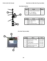
Page 39: ...tion Chamber Assembly w Burner HLC 600 700 Label Name Quan A 1 4 20 SS Hex Nut 1 B 1 4 SS Lock Washer 2 C 1 4 SS Fender Washer 2 E 6 SS Lock Washer 2 F 1 2 6 32 Machine Screw 2 D 3 4 1 4 20 SS Hex Bolt 2 G 8 SS Lock Washer 5 H 1 2 8 32 Machine Screw 1 I 8 32 SS Hex Nut 4 J 1 4 SAE 45 Flare Male Elbow Brass 1 K 1 4 NPT Elbow Brass 1 L 2 1 4 NPT Brass Nipple 1 M 1 4 NPT Street Elbow Brass 1 1 2 3 4 ...

Page 40: ...SS Machine Screw 4 B 6 SS Lock Washer 4 1 2 3 5 4 A C D E F Blower Assembly Recirculating Style Blower Assembly Vented Style 6 7 Label Name Part 4 Blower HLC 803 5 Sail Switch HLC 227 6 Sail Switch Mounting Brkt HLC 212 7 Blower Support Bracket HLC 800V 01 4 7 C F Blower Assembly Vented Style HLC 800V Label Name Quan C 1 2 6 32 SS Machine Screw 4 D 6 SS Lock Washer 4 E 1 2 8 32 SS Machine Screw 1 ...

Page 41: ...Fitting HLC 218 1 2 3 5 4 A Gas Valve Assembly Electrical Tray Assembly B C Label Name Part 4 Ignition Module w Relay HLC 918A 5 Electrical Tray HLC 901 6 Terminal Block HLC 404 7 Wiring Harness not shown HLC 920 Label Name Quan A 1 4 SAE 45 Male Connector 1 B 1 4 1 8 Bushing 1 C 1 4 NPT Hex Nipple 1 4 7 Electrical Tray Assembly including wiring HLC 900 6 ...

Page 42: ...7 Control Box above plus enclosure and wiring HLC 3 6 7 2 1 3 8 4 Control Box 110 V Standby 5 Electrical Mounting Plate N A 1 5 Control Box Electrical Assembly HLC 422 9 Label Name Part 8 Transformer HLC 504 9 Rectifier HLC 501 10 Changeover SPDT Relay HLC 230 11 Fuse Holder not shown HLC 427 12 Component Mounting Brkt N A 13 Capacitor HLC 233 14 110V Watertight Receptacle HLC 513 15 6x6 Enclosure...

Page 43: ...ted to Heater Chassis Ground LC Heater Wiring Diagram A11 Revision E 2011 HLC 420 High Temp Switch Electrical Tray HLC 900 Wiring Diagrams Parts List for HLC Heaters TH PWR BLO AIR 18ga Red 18ga Red 18ga Orange 18ga Brown 14ga Red 18ga White 18ga White 14ga Black 18ga White 18ga Yellow 18ga Black 18ga Blue 16ga Red 16ga Green Yelllow 16ga Red White Wire 14 3 Cord 14 3 Green ...

Page 44: ...hite 22ga Red 14ga Red A To 110V AC Plug in Hot Terminal B To 110V AC Plug in Neutral Terminal C To 110V AC Plug in Green Terminal D To 12V Constant Trailer Power E To 12V in Control Box F To Control Box and Heater Ground Control Box Wiring Diagram 110V Standby Wiring Assembly External Connections To 12V Heater From Heater Indicator To Heater Ground Revision E 2011 A12 12V Power In 14 2 White From...

Page 45: ... found to be defective as referenced above will be corrected as referenced in the previous paragraph at no charge for parts provided by original factory or labor but will include freight paid by buyer Failure to use original factory parts voids this warranty Elston Manufacturing Inc products received by Elston Manufacturing Inc after one 1 year from original shipment date to customer will be corre...

Page 46: ...ELSTON MANUFACTURING INC 706 N Weber Sioux Falls SD 57103 1 800 845 1385 www elstonmfg com ...

Reviews: