


25/02/2020
PIV LOFT IOM
Issue:
Saved Date:
A
Ø 150 /160
25/02/2020
PIV LOFT IOM
Issue:
Saved Date:
A
PIV UNIT
Ensure that flexible ducting is pulled taut and is not kinked or crushed. This will impact the performance of the unit and may cause noise.
1
2
3
4
5
7
6
3rd ANGLE PROJECTION
DO NOT SCALE-IF IN DOUBT, ASK!
DRAWING No.
SHEET
OF
ISSUE
DRAWN BY
DATE
SCALE
STATUS
APPROVED
CHECKED
FINISH
MATERIAL
SPECIFICATION
DIMENSIONS ARE IN mm UNLESS STATED OTHERWISE
THIS IS A C.A.D. PRODUCED DRAWING
AND THEREFORE NO SUBSEQUENT
MANUAL MODIFICATIONS WILL BE
ALLOWED.
TITLE
UNLESS OTHERWISE STATED.
BY
ISS
CN.
DATE
CHKD
ISS
CN.
BY
DATE
CHKD
ISS
CN.
BY
DATE
CHKD
ISS
CN.
BY
DATE
CHKD
A
1
B
C
D
E
F
G
2
3
4
5
7
6
7
6
5
4
3
2
1
A
C
B
E
F
G
DATE
ISS
CN.
CHKD
DATE
BY
ISS
CN.
CHKD
BY
DATE
ISS
CN.
CHKD
DATE
BY
CN.
ISS
CHKD
BY
SEE PARTS
SEE PARTS
1
1
B
AES
15/08/2019
PB
-
I
USED ON
OF THESE VIEWS FOR MANUFACTURING
PURPOSES ARE AT SUPPLIERS RISK.
REFERENCE PURPOSES ONLY. USE
ANY DEVELOPMENT VIEWS SHOWN ON
THIS DRAWING ARE SHOWN FOR
ORIENTATION OF FAN MUST BE AS PER
DRAWING OR REFER TO ELTA
GENERAL
ā 1.0
TOLERANCES
SEE PARTS
D
in writing from its owners Elta Fans Ltd.
purpose other than that for which it is supplied
specification document which is supplied in
confidence and which must not be used for any
and must not be reproduced without permission
Elta Fans Ltd. own the copyright of this drawing/
Tel. 01489 566500 Fax. 01489 566555
FAREHAM, HAMPSHIRE. PO15 5ST.
SEGENSWORTH INDUSTRIAL ESTATE,
17 BARNES WALLIS ROAD,
ELTA FANS LTD,
C
SANO PIV LOFT
A3
A3
SANO PIV LOFT IOM VIEWS
2:3
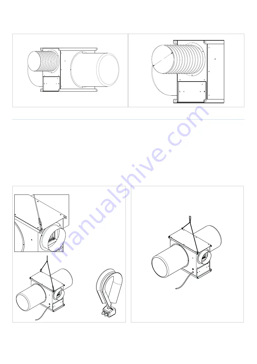
HANGING KIT
The SANO PIV LOFT is provided with a hanging kit comprising either a steel wire with carabiners or a single nylon cord.
The kit is not intended for use by persons (including children) with reduced physical, sensory or mental capacities or those with a lack of experience
and knowledge, unless they have been given supervision or instruction concerning use of the kit from a person responsible for their safety.
Children should be supervised to ensure that they do not play with the device.
Ensure the hanging cord suspends the unit in a safe and accessible location from a suitable and secure fixing point.
Hanging the unit safely and correctly is the responsibility of the installer. All fixings, and knots in the cord if used, must be secure and strong enough
to hold the weight of the unit.
1.
Ensure that the carabiners are securely attached to diagonally
opposite pre-punched holes.
2.
To link the 2 ends of the steel wire insert them both into the
securing clamp and tighten with a screwdriver.
3.
Use loop to hang off of a suitably sized screw/nail.
1.
Take the cord thread through diagonally opposite
pre-punched holes.
2.
Tie a suitable knot at each end to prevent loosening.
3.
Take the centre of the cord, pinch and knot creating a loop.
4.
Use loop to hang off of a suitably sized screw/nail.
Steel wire with carabiners
Nylon cord
1
2
3
4
5
7
6
3rd ANGLE PROJECTION
DO NOT SCALE-IF IN DOUBT, ASK!
DRAWING No.
SHEET
OF
ISSUE
DRAWN BY
DATE
SCALE
STATUS
APPROVED
CHECKED
FINISH
MATERIAL
SPECIFICATION
DIMENSIONS ARE IN mm UNLESS STATED OTHERWISE
THIS IS A C.A.D. PRODUCED DRAWING
AND THEREFORE NO SUBSEQUENT
MANUAL MODIFICATIONS WILL BE
ALLOWED.
TITLE
UNLESS OTHERWISE STATED.
BY
ISS
CN.
DATE
CHKD
ISS
CN.
BY
DATE
CHKD
ISS
CN.
BY
DATE
CHKD
ISS
CN.
BY
DATE
CHKD
A
1
B
C
D
E
F
G
2
3
4
5
7
6
7
6
5
4
3
2
1
A
C
B
E
F
G
DATE
ISS
CN.
CHKD
DATE
BY
ISS
CN.
CHKD
BY
DATE
ISS
CN.
CHKD
DATE
BY
CN.
ISS
CHKD
BY
SEE PARTS
SEE PARTS
1
1
B
AES
15/08/2019
PB
-
I
USED ON
OF THESE VIEWS FOR MANUFACTURING
PURPOSES ARE AT SUPPLIERS RISK.
REFERENCE PURPOSES ONLY. USE
ANY DEVELOPMENT VIEWS SHOWN ON
THIS DRAWING ARE SHOWN FOR
ORIENTATION OF FAN MUST BE AS PER
DRAWING OR REFER TO ELTA
GENERAL
ā 1.0
TOLERANCES
SEE PARTS
D
in writing from its owners Elta Fans Ltd.
purpose other than that for which it is supplied
specification document which is supplied in
confidence and which must not be used for any
and must not be reproduced without permission
Elta Fans Ltd. own the copyright of this drawing/
Tel. 01489 566500 Fax. 01489 566555
FAREHAM, HAMPSHIRE. PO15 5ST.
SEGENSWORTH INDUSTRIAL ESTATE,
17 BARNES WALLIS ROAD,
ELTA FANS LTD,
C
SANO PIV LOFT
A3
A3
SANO PIV LOFT IOM VIEWS
1:4
1
2
3
4
5
7
6
3rd ANGLE PROJECTION
DO NOT SCALE-IF IN DOUBT, ASK!
DRAWING No.
SHEET
OF
ISSUE
DRAWN BY
DATE
SCALE
STATUS
APPROVED
CHECKED
FINISH
MATERIAL
SPECIFICATION
DIMENSIONS ARE IN mm UNLESS STATED OTHERWISE
THIS IS A C.A.D. PRODUCED DRAWING
AND THEREFORE NO SUBSEQUENT
MANUAL MODIFICATIONS WILL BE
ALLOWED.
TITLE
UNLESS OTHERWISE STATED.
BY
ISS
CN.
DATE
CHKD
ISS
CN.
BY
DATE
CHKD
ISS
CN.
BY
DATE
CHKD
ISS
CN.
BY
DATE
CHKD
A
1
B
C
D
E
F
G
2
3
4
5
7
6
7
6
5
4
3
2
1
A
C
B
E
F
G
DATE
ISS
CN.
CHKD
DATE
BY
ISS
CN.
CHKD
BY
DATE
ISS
CN.
CHKD
DATE
BY
CN.
ISS
CHKD
BY
1
1
USED ON
OF THESE VIEWS FOR MANUFACTURING
PURPOSES ARE AT SUPPLIERS RISK.
REFERENCE PURPOSES ONLY. USE
ANY DEVELOPMENT VIEWS SHOWN ON
THIS DRAWING ARE SHOWN FOR
ORIENTATION OF FAN MUST BE AS PER
DRAWING OR REFER TO ELTA
GENERAL
ā 1.0
TOLERANCES
D
in writing from its owners Elta Fans Ltd.
purpose other than that for which it is supplied
specification document which is supplied in
confidence and which must not be used for any
and must not be reproduced without permission
Elta Fans Ltd. own the copyright of this drawing/
Tel. 01489 566500 Fax. 01489 566555
FAREHAM, HAMPSHIRE. PO15 5ST.
SEGENSWORTH INDUSTRIAL ESTATE,
17 BARNES WALLIS ROAD,
ELTA FANS LTD,
C
A3
A3
PivWireClamp
1:1


