Appe
ndix
Appendix
User's Manual
BAB
740
7—9
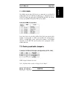
7.1.9 PCI IDSEL
The IDSEL input of each PCI device is connected to one of the PCI
address/data lines for individual addressing in configuration space.
Table XX shows the connection of the IDSEL signal for the various
devices on the BAB 740 and the PMC carrier board.
Table 38: IDSEL Connection
Device
Number
IDSEL Device
0 -
MPC106
11 AD(11)
W83C553F
13 AD(13)
SYM53C860
14 AD(14)
21143
15
AD(15)
PMC Slot 0
16
AD(16)
PMC Slot 1
30 AD(30)
Universe
II
Note that the device numbers differ from Intel convention where
number 0 corresponds to AD(11) and number 20 corresponds to
AD(31). Configuration cycles with device number 0 are handled
internally in the MPC106 and therefore don‘t correspond with a
address/data line.
7.2
Factory-settable Jumpers
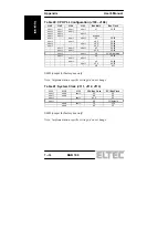
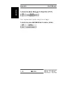
Table 39: CPU Drive Strength Configuration (J101, J102)
J102 J101
Description
short short
disabled
short - normal
(default)
- short
strong
- - herculean
SMD jumper for factory use only
Note: Implementation specific settings; do not change!
Summary of Contents for BAB 740
Page 1: ...BAB 740 Basic Automation Board with PowerPC 740 manual Revision 2C...
Page 11: ...User s Manual Table of Contents BAB 740 V 7 1 9 PCI IDSEL 7 9 7 2 Factory settable Jumpers 7 9...
Page 16: ...Table of Contents User s Manual BAB 740 X...
Page 22: ...Specification Specification User s Manual BAB 740 1 6...
Page 42: ...Connector Assignments User s Manual BAB 740 3 16 Connector Assignments...
Page 50: ...Board Parameters Board Parameters User s Manual BAB 740 4 8...
Page 60: ...Booting Booting User s Manual BAB 740 6 4...
Page 74: ...NOTES...


