background image

SECTION 2 - - - INSTALLATION AND OPERATION

2.1

INTRODUCTION AND PRECAUTIONS

Before installing the telescope, please read this section carefully.  Should any difficulties arise, contact your supplier or
Technical Support staff at Eltec Instruments directly.

IMPORTANT NOTICES FOR INSTALLATION AND SERVICE PERSONNEL:

Handle the telescope with care

The unit is a precision instrument and will not function to its specifications if subjected to mechanical shock or undue
stress.

DO NOT point the unit into the sun or other intense source of infrared radiation

The telescope contains precision optical components that focus infrared energy onto very sensitive pyroelectric
components.  Intense sources of infrared will destroy these components and possibly damage the optics.

DO NOT touch the front window with bare hands

Salts and acids from the hands may damage the surface of the window.  To clean the window, use only a soft, clean
cloth.  Cloth may be moistened with distilled water or alcohol in severe conditions.  Clean the window very gently, do not
apply undue pressure as the window is fragile and may be damaged or broken.

Use precautions in lightning storms

In lightning prone areas, take measures to arrest lightning discharges and electrostatic buildup.

2.2

UNPACKING

Remove the unit from the shipping container and carefully check for signs of damage.  Any such damage should be
reported to your supplier or to the Technical Support staff at Eltec Instruments directly.  Do not attempt to install a damaged
unit until advice has been obtained.

2.3

POWER REQUIREMENTS

The telescope can be used over a wide voltage range from 3.0V to 15V DC.  The voltage must be DC, any ripple on the
supply voltage will be present at the output of the telescope.  Avoid running low voltage DC next to AC power cables over
long distances.  Induced AC ripple and noise in the DC supply will be present at telescope’s output.

2.4

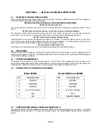
CONNECTION TO EXTERNAL EQUIPMENT

2.5

TAMPER SENSE (MODEL 860M5 AND 860M6 ONLY)

The difference between the Model 860M5 and the Model 860M6 are the internal tamper sense connections.  The Model
860M5 tamper sense connects to V+ through a 2 megohm resistor.  The Model 860M6 tamper sense is connected to
ground.

Page 7

PIN

DESIGNATION

A

OUTPUT

B

GROUND

C

OUTPUT

D

V+ (3 TO 15V DC)

E

N/C

F

N/C

PIN

DESIGNATION

A

OUTPUT

B

GROUND

C

OUTPUT

D

V+ (3 TO 15V DC)

E

N/C

F

TAMPER SENSE

Model 860M5 and 860M6

Model 860M1

Summary of Contents for IR-EYE 860M1

Page 1: ...mate with Contractor Developed Signal Processing or Legacy Systems Model 860M1 Model 860M5 Model 860M6 Please note These telescopes do not provide either relay or TTL outputs They are made available for special signal processing systems For units that do provide relay and TTL outputs see Eltec Models 864 and 864M3 ...

Page 2: ...THIS PAGE LEFT INTENTIONALLY BLANK ...

Page 3: ...SE ALARM SOURCES SECTION 2 INSTALLATION AND OPERATION 2 1 INTRODUCTION AND PRECAUTIONS 2 2 UNPACKING 2 3 POWER REQUIREMENTS 2 4 CONNECTION TO EXTERNAL EQUIPMENT 2 5 TAMPER SENSE MODEL 860M5 AND 860M6 ONLY 2 6 AMPLIFICATION REQUIREMENTS 2 7 MECHANICAL OUTLINE 2 8 MOUNTING 2 9 MOUNTING AND ACCESSORIES 2 10 OPERATION 2 11 ALIGNMENT 2 12 WALK TESTING 2 13 WALK TESTING FIELD OF VIEW 2 14 MAINTENANCE 2 ...

Page 4: ... application may require a broadening of that range with a consequent increase in noise Eltec recommends that you AC couple the telescope s analog output The current draw per channel should be typically 8 microamps 1 2 BASICS OF PASSIVE INFRARED PIR DETECTION Each person object or animal emits infrared energy as a function of its surface temperature and size For temperatures around ambient the max...

Page 5: ...rature contrast can be as little as 1o C or less either positive or negative for a person at the nominal distance of 500ft to trigger the alarm A precison mirror focuses the radiation onto a twin channel pyroelectric detector which will produce a defined signal from a moving target Two stage optical filtering restricts the radiation to the atmospheric window 8 14 microns where the effects of the n...

Page 6: ...nfrared signal attenuation can almost be neglected for points 1 to 9 on the International Visibility Scale see Table 1 corresponding to dense fog and perfectly pure air respectively Only for visibility 0 very dense fog will the attenuation be significant but detection range will still be typically up to 50 more than the distance the human eye will see Page 3 DISTANCE COVERAGE X SIZE Y SIZE 100 ft ...

Page 7: ...vided into portions of 300 ft each being covered by one telescope see Fig 1 4 This kind of set up will give reliable detection under virtually all climatic conditions It is important to note that the range of the telescope is not limited by but a function of size and temperature of the target A car or an airplane may trigger an alarm when crossing the field of view at a mile distance depending on ...

Page 8: ...g wave infrared See Fig 1 8 1 9 POTENTIAL FALSE ALARM SOURCES Various sources may affect the performance of an outdoor security system For instance DO NOT aim the telescope into the horizon straight out UNLESS you are aiming into a wall the side of a building or an embankment that is within your monitored perimeter Although the telescope will detect a person at 500 feet under most conditions it ma...

Page 9: ...trips the first thing to check after verifying that there is proper voltages to electronics and telescope is the aiming to make sure that detection of motion of distant objects is not the source of unwanted alarm signals REFER TO OPERATION AND ALIGNMENT SECTIONS Passive infrared detection can perform exceptionally well under almost all conditions Page 6 Figure 1 9 Grounding with Actual Terrain Tel...

Page 10: ... damaged or broken Use precautions in lightning storms In lightning prone areas take measures to arrest lightning discharges and electrostatic buildup 2 2 UNPACKING Remove the unit from the shipping container and carefully check for signs of damage Any such damage should be reported to your supplier or to the Technical Support staff at Eltec Instruments directly Do not attempt to install a damaged...

Page 11: ...3µF C6 1 54K R4 3 3µF C3 V 5 TO 15V GND ANALOG OUTPUT 100K 100µF C1 ANALOG OUTPUT 13K R5 13K R10 6 81M R7 6 81M R2 C2 2 2nF 1Hz TO 10Hz SINGLE SUPPLY AMP WITH GAIN OF 500 NOTES ALL CAPACITORS ARE 10 10V ALUM EXCEPT FOR C2 AND C5 CAPACITORS C1 AND C4 MUST HAVE A LEAKAGE 1µA ALL RESISTORS ARE 1 1 4W MFLM AMPLIFIER MAY HAVE TURN ON TIME OF SEVERAL MINUTES OFFSET WILL BE ONE HALF OF V ADJUST RATIO OF ...

Page 12: ...r stable mounting and easy aiming the following accessories can be supplied Page 9 Double Mounting Bracket No AO54M1 The part clasping the telescope is fixed to a platform with a nut for adjustment of the elevation The other part is fixed to the pole with 360 o rotation capability for aiming the telescope to any desired direction Suitable for pole diameters of 1 5 to 3 0 inches Mounting Bracket No...

Page 13: ...lescope does not alarm through the trouble period when blinded then the actual field of view should be verified by walk testing to insure that the telescope is not picking up distant vehicles or motion from an adjacent area In addition many telescope users have used the scope output to trigger a recording CCTV system with time date stamp for alarm source verification This approach is highly recomm...

Page 14: ...SEMBLY WILL COMPROMISE THE SEAL AND VOID THE WARRANTY 2 15 MODEL 860M1 860M5 860M6 SPECIFICATIONS Mechanical Weight 2 lbs 12 oz Size 3 50 8 89 cm dia x 12 93 32 84 cm long Enclosure Painted PVC hermetically sealed Color O D Green other colors available as special order Optical Nominal Range 500 ft 152 m with appropriate customer supplied electronics Spectral Response 8 to 14 microns double filtere...

Page 15: ...cinstruments com ELTEC INSTRUMENTS INC 07 2017 Printed in U S A Form DS860M1 5 6 E 07 2017 NOTICE The information provided herein is believed to be reli able However ELTEC Instruments Inc assumes no responsibility for inaccuracies or omissions Due to industry components being incorporated into ELTEC s devices and ELTEC continually striving for product improvement specifications may change without ...

Page 16: ...4 10 km 0 4 0 7 Moderate rain very light snow thin haze 7 Good 10 20 km 0 7 0 8 Light rain no precipitation 8 Very Good 20 50 km 0 8 0 9 No precipitation 9 Exceptional 50 km 0 9 1 0 Perfectly pure air Notes 1 The transmittance refers to λ 0 61 µ 2 The values for 0 3 points are rough estimates due to meager experimental data Bramson Infrared Radiation Plenum Press N Y 1968 TABLE 1 ELTEC Instruments...

Reviews: