deployed worldwide for over two decades in security systems for industrial, governmental and military
installations. The rugged, watertight, hermetically sealed construction of these telescopes make
them ideal for outdoor applications. The telescope’s use of state-of-the-art detector technology and
precision optics, coupled with advanced signal processing optimizes the discrimination of moving
targets from other events. This technology is an exciting alternative to microwave or active infrared
links and is also ideal in critical applications where dual technologies are desired. The simple
installation process, and the variety of options available, make these telescopes well suited for a
number of applications, some of which include detection of personnel, vehicles, boats, airplanes,
fires, explosions, etc. The telescopes can be used in both fixed and temporary installations to monitor
events at long distances.
1.4
FUNCTION
A person or vehicle will always have a temperature contrast in respect to the background, producing
a change of radiation within the field of view when passing through it. This temperature contrast can
be as little as 1
o
C or less (either positive or negative) for a person at the nominal distance of 500ft
to trigger the alarm. A precison mirror focuses the radiation onto a twin channel pyroelectric detector
which will produce a defined signal from a moving target. Two stage optical filtering restricts the
radiation to the "atmospheric window" (8 - 14 microns) where the effects of the normal constituents
of the atmosphere (particularly humidity) least affect the transmission of infrared radiation. This
double optical filtering minimizes unwanted radiation from sunlight or headlights which otherwise may
produce false alarms.
1.5
FIELD-OF-VIEW
Please note: This manual discusses installation and operation of the Model 860M1, 860M5 and
860M6 telescopes. The field of view is the same for all models. The difference between the models
is that the 860M5 and 860M6 have the added tamper sense feature.
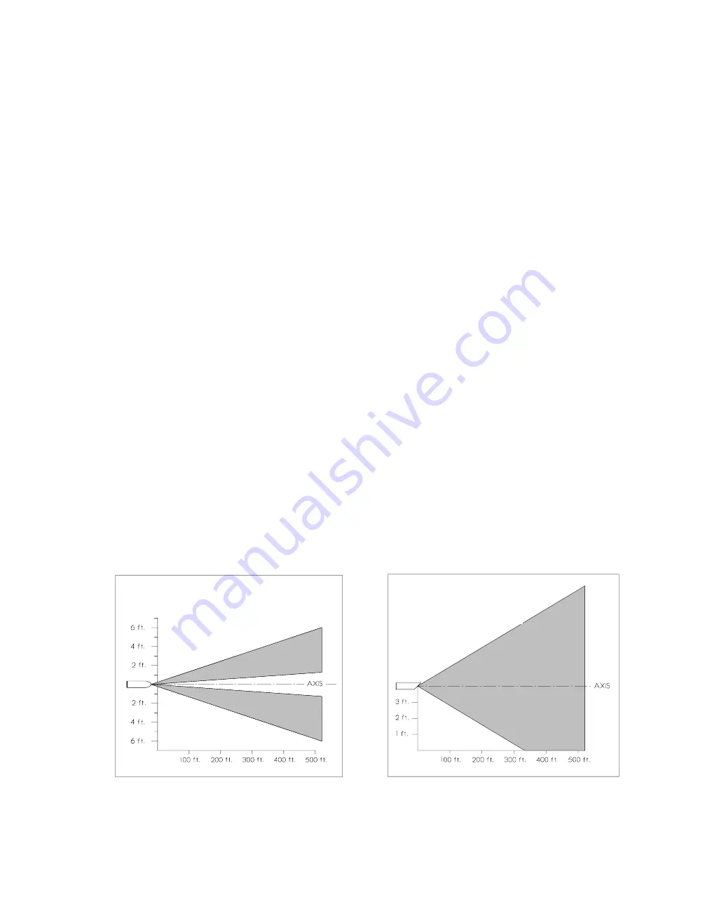
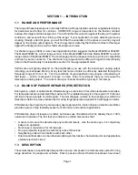
The field of view consists of two distinct segments. The area covered as a function of distance is
shown in Figs 1.1, 1.2 and 1.3. This standard field of view is ideally suited for observation of a defined
spot from a distance.
Figure 1.2
Figure 1.1
Vertical Coverage
Side View Detail
Horizontal Coverage
Top View Detail
Page 2
Data is calculated and subject to variations in environmental changes


