24
ESR Series Routers Operation Manual
3.3
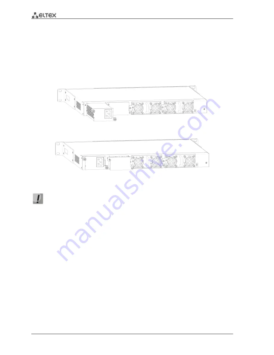
ESR-1000, ESR-1200 power module installation
ESR-1000 router can operate with one or two power modules. The second power module
installation is necessary when the device operates under strict reliability requirements.
From the electric point of view, both places for power module installation are identical. In the
context of device operation, the power module located closer to the edge is considered as the main
module, and the one closer to the centre—as the backup module. Power modules can be inserted and
removed without powering the device off. When additional power module is inserted or removed, the
router continues operation without reboot.
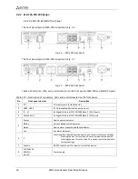
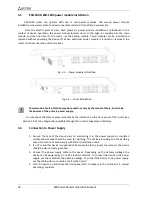
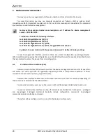
Fig. 3.3
—
Power module installation
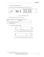
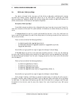
Fig. 3.4
—
Cover installation
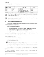
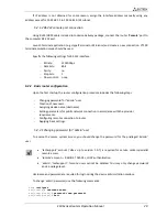
Power module fault indication may be caused not only by the module failure, but also by
the absence of the primary power supply.
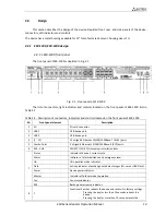
You can check the state of power modules by the indication on the front panel of the router (see
Section 2.4.3) or by diagnostics, available through the router management interfaces.
3.4
Connection to Power Supply
1.
Ground the case of the device prior to connecting it to the power supply. An insulated
multiconductor wire should be used for earthing. The device grounding and the earthing
wire cross-section should comply with Electric Installation Code.
2.
If a PC or another device is supposed to be connected to the router console port, the device
should be also securely grounded.
3.
Connect the power supply cable to the device. Depending on the delivery package, the
device can be powered by AC or DC electrical network. To connect the device to AC power
supply, use the cable from the delivery package. To connect the device to DC power supply,
use the cable with cross-section not less than 1mm
2
.
4.
Turn the device on and check the front panel LEDs to make sure the terminal is in normal
operating conditions.

