18
Chapter 6.
Design
6.1
Front Panel
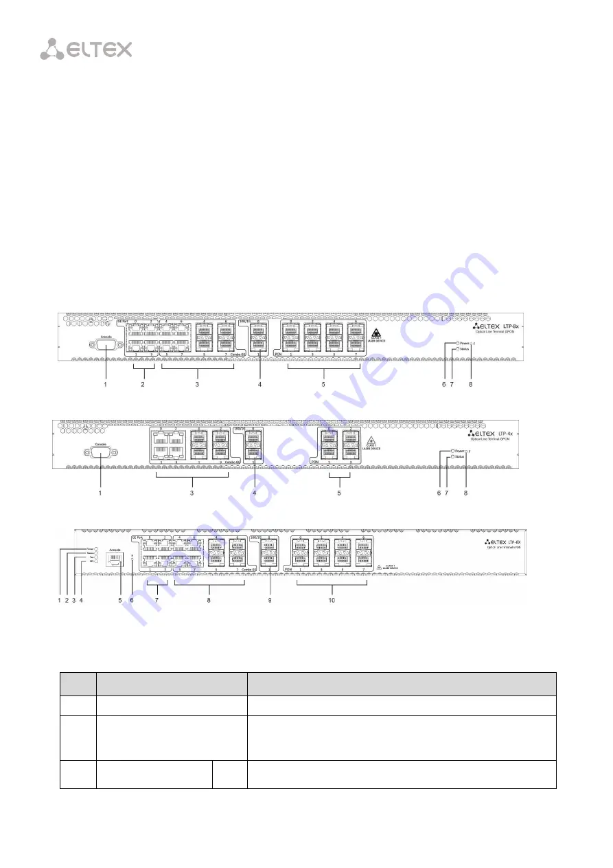
The device has a metal case available for 19” form-factor rack-mount 1U shelf installation. The
front panel of the terminal is shown in Fig. 6.1, Fig. 6.2, and Fig. 6.3. Tables 6.1 and 6.2 list
connectors, LEDs, and controls located on the front panel.
Fig. 6.1 – Front Panel of the LTP-8X/LTP-8X rev. B Terminal
Fig. 6.2 – Front Panel of the LTP-4X Terminal
Fig. 6.3 – Front Panel of the LTP-8X rev. C Terminal
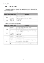
Table 6.1 – Description of the Connectors, LEDs, and Controls Located on the Front Panel of LTP-8X,
LTP-4X/8X rev. B
No.
Component
Description
1
Console
RS-232 port for local control of the terminal
2
GE Port 0..3
4 RJ-45 connectors of 10/100/1000Base-T Gigabit uplink
interface for connection to IP networks (for LTP-8X)
3
Combo GE
0..3
4 chassis for SFP modules of 1000Base-X uplink interface for
Summary of Contents for LTP-4X
Page 11: ...11 Part I General ...
Page 29: ...29 Part II Getting Started with the Terminal ...
Page 37: ...37 Part III Configuring the Terminal ...
Page 98: ...98 Part IV ONT Configuration ...
Page 174: ...174 Part V Terminal Monitoring ...
Page 189: ...189 Part VI Terminal Maintenance ...
Page 191: ...191 Step 2 Remove the module from the slot Fig 43 4 Removing SFP Transceivers ...


