21
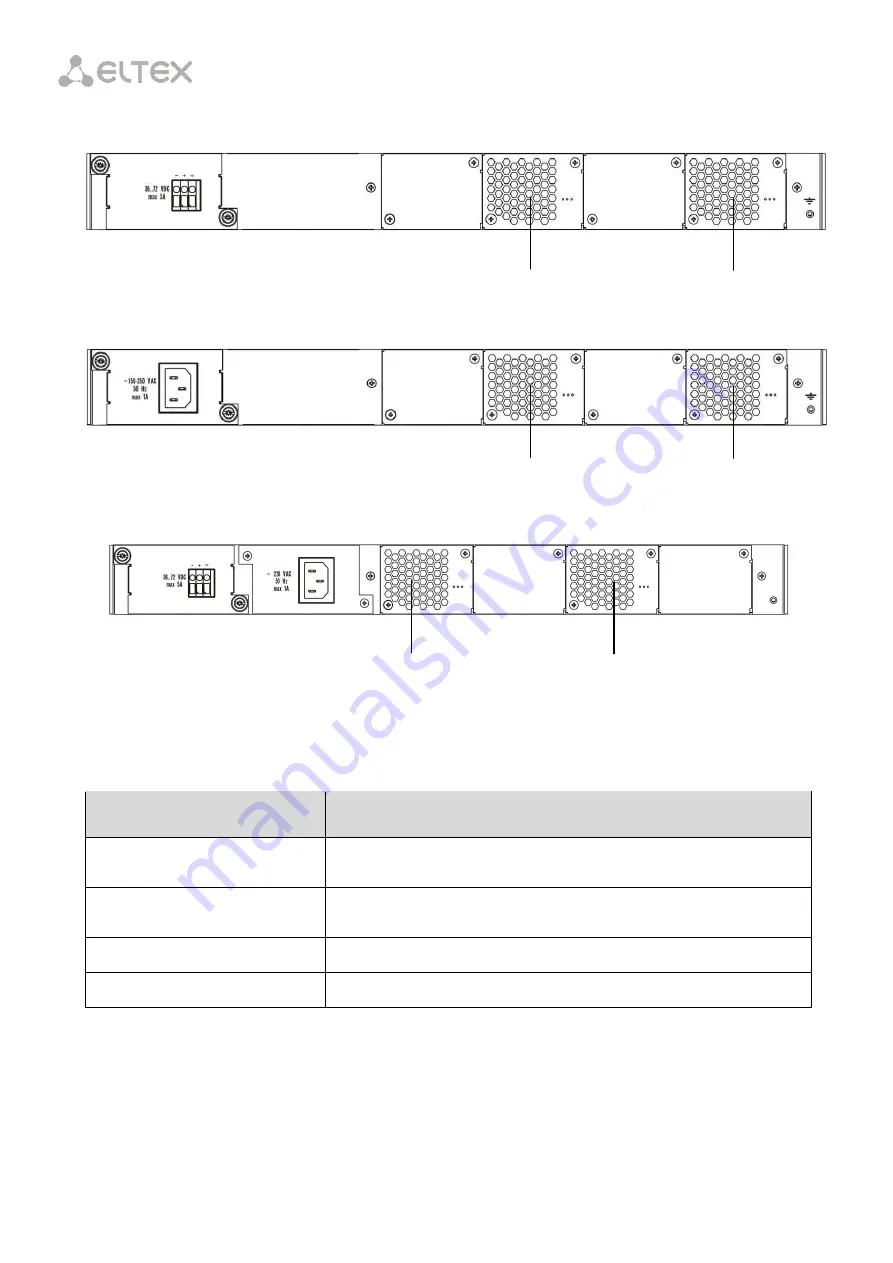
Table 6.3 lists rear panel connectors.
Fig. 6.4 – Rear Panel of the LTP-4X/8X (DC) Optical Line Terminal
Fig. 6.5 – Rear Panel of the LTP-4X/8X (AC) Optical Line Terminal
Fig. 6.6 – Rear Panel of the LTP-4X/8X rev. C Optical Line Terminal with Two Power
Modules
Table 6.3 – Description of the Rear Panel Connectors
Component
Description
36.. 72 VDC, max. 5 A
Connector for DC power supply
160–250 VAC, 50 Hz, max. 1 A
Connector for AC power supply
Fan0, Fan1
Ventilation units
Earth bonding point
Earth bonding point of the terminal
fan1
fan0
fan1
fan0
fan1
fan0
Summary of Contents for LTP-4X
Page 11: ...11 Part I General ...
Page 29: ...29 Part II Getting Started with the Terminal ...
Page 37: ...37 Part III Configuring the Terminal ...
Page 98: ...98 Part IV ONT Configuration ...
Page 174: ...174 Part V Terminal Monitoring ...
Page 189: ...189 Part VI Terminal Maintenance ...
Page 191: ...191 Step 2 Remove the module from the slot Fig 43 4 Removing SFP Transceivers ...


