25
2.
PC and measurement instruments should be grounded prior to connection to the terminal. The
potential difference between the terminal case and the cases of the instruments should be less
than 1 V.
3.
Prior to turning the terminal on, ensure that all cables are undamaged and securely connected.
4.
Make sure the device is off when installing or removing the case.
5.
Power modules of LTP-X, LTP-X rev. B should be replaced only when the device is powered off. Follow
the procedure in Section 7.2. Power modules of LTP-X rev. C terminals can be installed and removed
without powering the device off.
6.
Follow the instructions given in Chapter 36 to install or remove SFP transceivers. This operation does
not require the terminal to be turned off.
7.2
Terminal Installation
Check the terminal for visible mechanical damage before installing and turning the terminal on. In case of
any damage, stop the installation, fill in a corresponding document, and contact your supplier. If the terminal
was exposed to low temperatures for a long time before installation, leave it for 2 hours at ambient
temperature prior to operation. If the terminal was exposed to high humidity for a long time, leave it for at
least 12 hours in normal conditions prior to turning it on.
Support Brackets Mounting
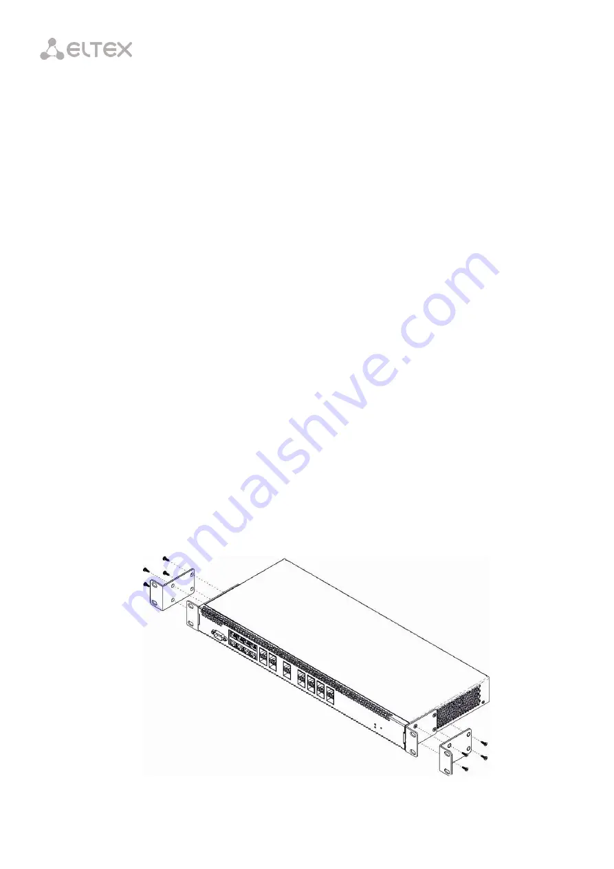
The delivery package includes support brackets for rack installation and mounting screws to fix the
terminal case on the brackets. To install the support brackets:
Step 1.
Align four mounting holes in the support bracket with the corresponding holes in the side panel of
the device.
Step 2.
Use a screwdriver to screw the support bracket to the case.
Step 3.
Repeat steps 1 and 2 for the second support bracket.
Fig. 7.1 – Support Brackets Mounting
Summary of Contents for LTP-4X
Page 11: ...11 Part I General ...
Page 29: ...29 Part II Getting Started with the Terminal ...
Page 37: ...37 Part III Configuring the Terminal ...
Page 98: ...98 Part IV ONT Configuration ...
Page 174: ...174 Part V Terminal Monitoring ...
Page 189: ...189 Part VI Terminal Maintenance ...
Page 191: ...191 Step 2 Remove the module from the slot Fig 43 4 Removing SFP Transceivers ...


