User manual for NV-510-WB 10
Table 3 – Description of connectors and controls located on the rear panel of the device
Rear panel element
Description
1
ON/OFF
The button for switching the device on/off
2
5V
Connector for power adapter
3
HDMI
HDMI connector for transmitting high-quality digital video and audio signals to
the TV.
4
LAN 10/100/1000
RJ-45 connector of LAN Ethernet for connection to a service provider network.
5
IR
A connector for an external IR receiver.
2.2.1
Ethernet port light indication
The status of Ethernet interfaces is indicated by LEDs built into the 10/100/1000 connector.
Figure 4 – RJ-45 connector
Table 4 – Light indication of Ethernet interfaces
ACT indicator
LINK indicator
Ethernet interface status
Off
Off
The port is off or the connection is not estab-
lished
Off
Blinks
Data transfer in 100BASE-T mode
Blinks
Off
Data transfer in 10BASE-T mode
Blinks
Blinks
Data transfer in 1000BASE-T mode
2.3
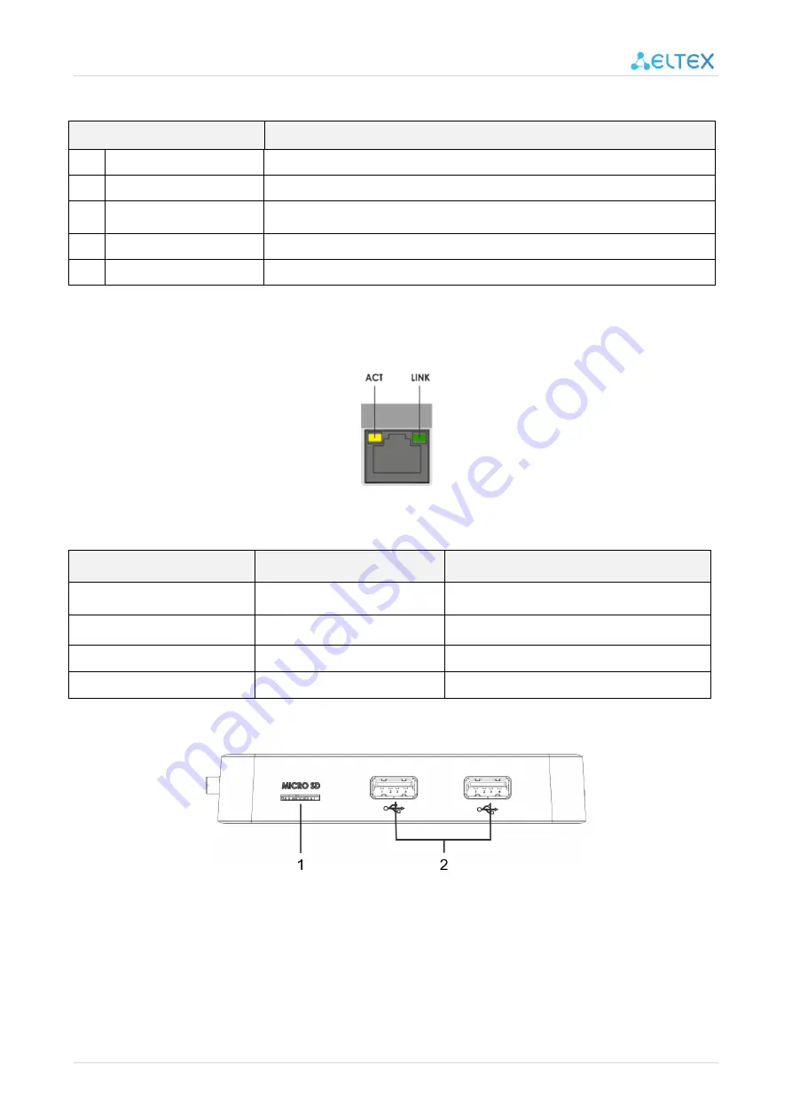
Front panel of the device
Figure 5 – Side panel of the device


