____________________________________________________________________________________
____________________________________________________________________________________
TAU-4M.IP Subscriber gateway
13
1.5.2
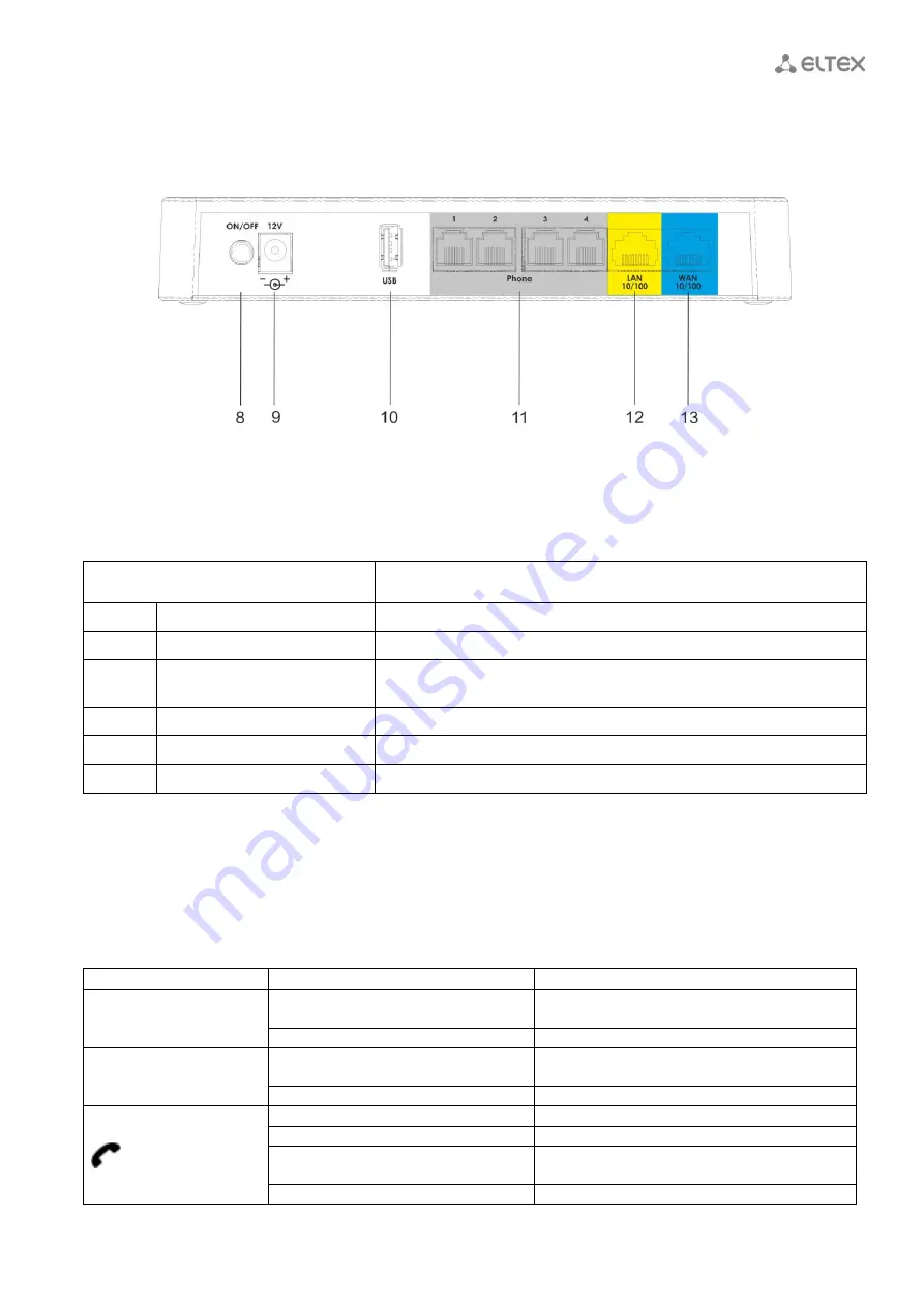
Rear panel of the device
The
TAU-4M.IP
rear panel appearance is shown in Figure 5.
Figure 5 -
TAU-4M.IP
rear panel appearance
Connectors and controls located on
TAU-4M.IP
rear panel are described in Table 3.
Table 3 – Description of connectors and controls located on
TAU-4M.IP
rear panel
Rear panel element
Description
8
ON/OFF
ON/OFF switch
9
12V
Power adapter connector
10
USB
USB port for external USB device connection (USB flash, external HDD,
3G/4G USB modem)
11
Phone
4 x RJ-11 ports for analogue phone connection
12
LAN
10/100BASE-T Ethernet (RJ-45) port for local network device connection
13
WAN
10/100BASE-T Ethernet (RJ-45) port for external network connection
1.6
Light indication
WAN, LAN, Phone, Power
indicators located on
TAU-4M.IP
top panel show the device current status.
Table 4 lists possible states of the LEDs.
Table 4 - Light indication of
TAU-4M.IP
states
Indicator
Indicator State
Device state
WAN
Solid (green - 10 Mbps, orange -
100Mbps)
Connection between station terminal and
subscriber device is established
Flashes
Packet data transmission via WAN interface
LAN
Solid (green - 10 Mbps, orange -
100Mbps)
Connection to the network device is established
Flashes
Packet data transmission via LAN interface
Green, solid
Phone is off-hook (line is active)
Off
Phone is on-hook, normal operation
Green, flashes with 20Hz frequency for
second, then 4seconds pause.
Incoming call is on the phone port
Green flashes slowly in period
Subscriber port is not registered at SIP proxy


