background image

18

BA-en-4003-2005_TUE30

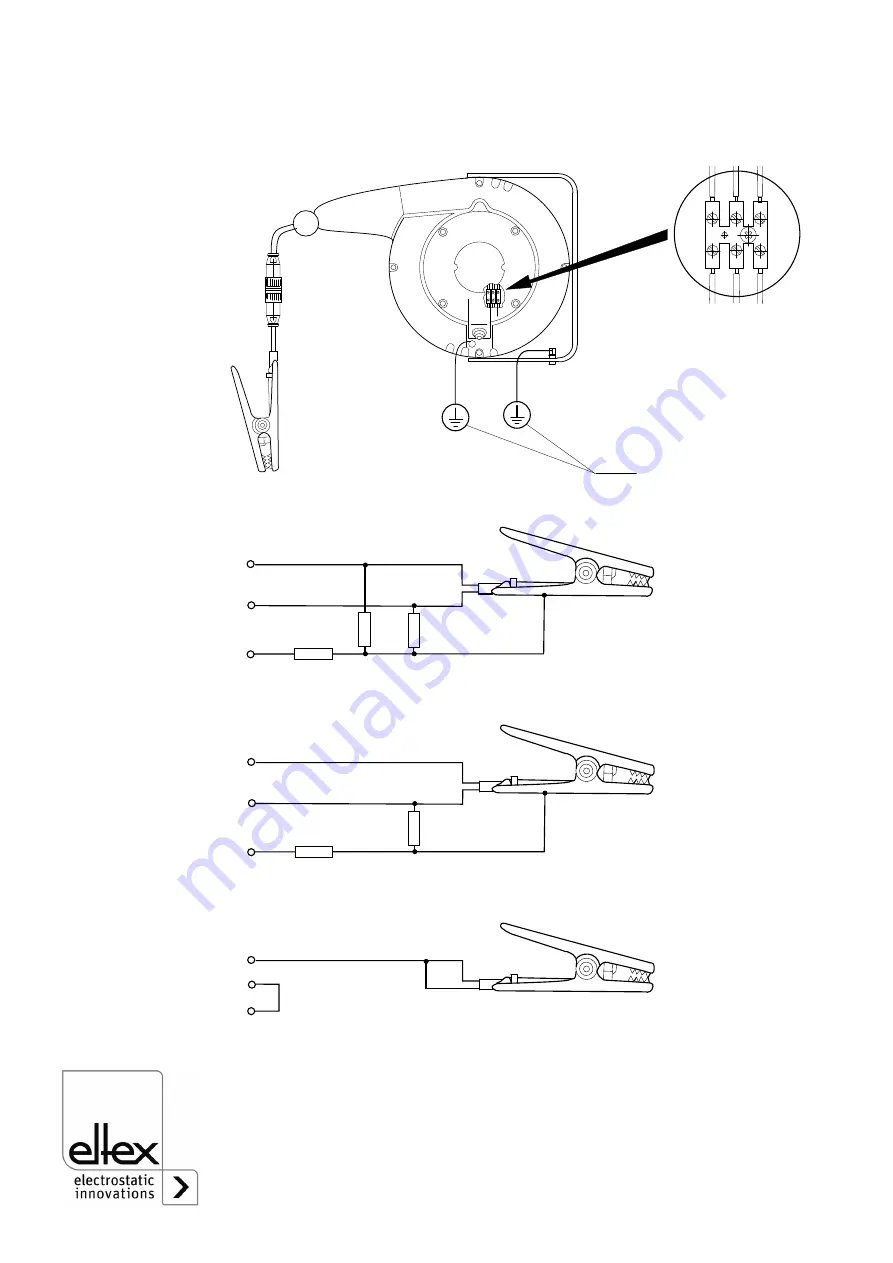
Connection to the cable rewinder

Connecting diagrams of the clamps

Wire color: a   blue

 b   brown   c   green/yellow

Fig. 6:
Connection of the 
cable rewinder 
601KR/_

z00

034

y

PAL

a

b

c

b a c

Fig. 7:
Connecting dia-
grams of the 
clamps type 70AG, 
70AK, 70BG and 
70HK

z00

036

y

100 k

a

b

c

100 k

100 k

70AG / 70AK

100 k

a

b

c

100 k

70BG

a

b

c

70HK

Summary of Contents for Terrabox TCB030

Page 1: ...Operating Instructions Terrabox TCB030 Terracompact II TCO030 for TUE30 Terra Control Ground Monitoring System BA en 4003 2005 F00034y ...

Page 2: ...2 BA en 4003 2005_TUE30 ...

Page 3: ...act II TCO030 19 3 2 1Assembly 19 3 2 2Electrical connections 19 3 2 3Power supply TCON01 24 3 3 Supply voltage 24 3 4 Cable specification 24 4 Operation 25 4 1 Start up 25 4 2 Function 25 4 3 Operation with 2 ground contactors Big Bag grounding 26 4 3 1Before connecting the two ground contactors the BIG BAG has no connection to ground potential 26 4 3 2Before connecting the two ground contactors ...

Page 4: ...rracompact II TCO030 33 8 3 Power supply TCON01 34 9 Dimensions 35 10 Accessories and spare parts 37 A Annex 39 A 1 Grounding with ground monitoring unit active grounding 39 A 2 Grounding without ground monitoring unit passive grounding 40 A 3 Overview 41 Declarations of Conformity 42 ...

Page 5: ... are considered to be adequately grounded if their ground leakage resistance is not greater than 105 108 The Eltex Terra Control Ground Monitoring System guarantees a safe and reliable ground connection Used in combination with the Eltex ground clamps and the cable rewinders the system provides the ultimate ground connection The Terra Control components monitor the connection to the bonding conduc...

Page 6: ...ewinder plastic 601KR KW with ground clamp zone 1 21 4 Ground clamp zone 1 21 5 Ground cable KG BNA zone 1 21 6 Helix ground cable KG BSA zone 1 21 7 TERRABOX TCB030 zone 1 21 Z00206y Fig 1 Overview TUE30 Terra ControlGround Monitoring System Explosion hazard area zone 1 2 safe area 2 3 4 Terrabox 5 Terracompact II 1 2 3 4 5 6 N O COM N C 24V DC 10 7 8 9 10 11 12 PAL input Ex i PAL ZG2 Z2 ZG1 Z1 1...

Page 7: ...DW 601KR KW cable rewinder Series 70 ground clamps see separate Operating Instructions BA en 4007 Ground clamps TERRACLAMP see separate Operating Instructions BA en 4014 1 2 Variants Terrabox TCB030 Standard 1 ground contactor TCB030 S0 24 V DC TCB030 S1 115 V AC TCB030 S2 230 V AC Operating points ON 20 kOhm OFF 50 kOhm 20 BIG BAG 1 ground contactor TCB030 B0 24 V DC TCB030 B1 115 V AC TCB030 B2 ...

Page 8: ...must be observed when operating the units in explosion hazard areas as specified in the approvals 2 2 Technical advance The manufacturer reserves the right to make changes to the technical specifications without prior notice in order to adapt the units to state of the art engineering Eltex will provide the latest information on any changes or modifications in the operating instructions on request ...

Page 9: ...ed for explosion hazard areas A Connect Disconnect Approval by the plant operator must be obtained before carrying out any installation assembly service repair or maintenance work in potentially explosive atmospheres Make sure that there is no potentially explosive atmosphere prevailing in the wor king area see chapter 3 Assembly and installation page 12 chapter 5 Maintenance page 28 Electrical sy...

Page 10: ...plate indicating the connection data supply vol tage of the units see chapter 4 Operation page 25 During operation with 2 ground contactors it is not only the ground link of the BIG BAG which is being monitored but also the conductivity of the BIG BAG Note that both ground contactors are connected to two different grounding points of the BIG BAG see chapter 4 3 Operation with 2 ground contactors B...

Page 11: ...s in which gas is likely to cause explosive atmospheres simple electrical apparatus like clamps and cable rewinders may be connected to the measuring circuit The simple apparatus must comply with the appropriate requirements of EN 60079 11 but must not be certified and marked The intrinsically safe measuring circuit may also be guided into the explosion hazard zone in which Class 1 operational equ...

Page 12: ... 1 1 View of appliance 1 Cable screw connection with kink guard Ex 2x for BIG BAG grounding 2 Cable inlet 3 Blanking plug 4 Ground terminal 5 Cable inlet 3x 6 Indicator lamp dual color green red 7 Mounting bracket 4x 8 Type plate Fig 2 Terrabox TCB030 Z00031y 1 2 3 4 5 6 7 8 ...

Page 13: ... view Avoid direct exposure to sunlight 3 1 3 Electrical connections When installing the system in explosion hazard areas every precaution must be taken to ensure that no explosive atmosphere exists in the working area The unit must always be connected to the equipotential bond via the external ground terminal 7 Fig 4 Fig 5 In addition the ground terminal inside the enclosure must be connected to ...

Page 14: ...ng to the intrinsically safe circuit see cable entry 2 Fig 4 Fig 5 The terminals of the Terrabox TCB030 are also marked as intrinsically safe terminals blue This is NO protective ground link the leads must NOT be coloured green yellow The PAL connection can be made with a two wire sheathed cable with no wire colours prescribed i e all colours apart from green yellow are permitted The sheathed cabl...

Page 15: ...age lead 7 Ground terminal 8 Equipotential lead 9 Supply voltage 24 VDC or 115 230 VAC see type plate 10 Contact position diagram no enabling indicator lamp red core colors a blue b brown c green yellow Fig 4 Connection example active grounding with clamp 70AG BG via cable rewinder 601KR _ z00033y P AL P AL NC NC NO NO COM COM N L L1 L Ex ia 1 2 4 5 6 7 c b a 601KR_ ZG1 Z1 ZG2 Z2 8 3 10 9 1 1 1 2 ...

Page 16: ...tage lead 7 Ground terminal 8 Equipotential lead 9 Supply voltage 24 VDC or 115 230 VAC see type plate 10 Contact position diagram no enabling indicator lamp red core colors a blue b brown c green yellow Fig 5 Connection example BIG BAG grounding with two clamps 70HK without cable rewinder z00035y P AL P AL NC NC NO NO COM COM N L L1 L Ex ia 1 2 4 5 6 7 a 3 70HK 70HK ZG1 Z1 ZG2 Z2 8 9 10 1 1 1 2 2...

Page 17: ...ly Clamp contact 2 Clamp contact 1 Clamp casing 1 Non intrinsically safe terminal block contact circuit indicator signal Terminal Connection relay contact NC relay 2 COM relay 2 NO relay 2 NC relay 1 COM relay 1 NO relay 1 Break contact 2 Middle contact 2 Make contact 2 Break contact 1 Middle contact 1 Make contact 1 Connection 24 V DC supply 24 V DC 0 V DC Connection 230 V AC supply 1 N 230 V AC ...

Page 18: ...ams of the clamps Wire color a blue b brown c green yellow Fig 6 Connection of the cable rewinder 601KR _ z00034y PAL a b c b a c Fig 7 Connecting dia grams of the clamps type 70AG 70AK 70BG and 70HK z00036y 100 k a b c 100 k 100 k 70AG 70AK 100 k a b c 100 k 70BG a b c 70HK ...

Page 19: ...ctrical connections Warning The signal contact supply lead and the operating voltage supply leads must not be allowed to cross the intrinsically safe circuits blue leads Separate cable conduits must be provided for intrinsically safe circuits The maximum cable length in the intrinsically safe circuit must not exceed the maximum rated capacity and inductance see Technical Specifications A potential...

Page 20: ...e intrinsically safe circuit see connection 7 and 8 Fig 9 The terminals of the Terrabox TCB030 are also marked as intrinsically safe terminals blue This is NO protective ground link the leads must NOT be coloured green yellow The PAL connection can be made with a two wire sheathed cable with no wire colours prescribed i e all colours apart from green yellow are permitted The sheathed cable can be ...

Page 21: ...2 not assigned if 1 clamp only Clamp contact 2 Clamp contact 1 Clamp casing 1 Non intrinsically safe terminal block contact circuit indicator signal Terminal Connection relay contact 3 4 NO 5 COM 6 NC not assigned Make contact Middle contact Break contact Connection 24 V DC supply 1 2 0 V DC 24 V DC Fig 9 Connecting the bonding conductor PAL Z00149y Terracompact II 1 2 3 4 5 6 N O COM N C 24V DC 1...

Page 22: ...h the equipotential bonding lead Connect the ground clamp via a plug type machine coupling and secure with a threaded joint IP67 A Explosive area B Safe area 1 Two fixed wiring terminals to PAL 1 5 mm2 2 To the DC power supply 3 Floating output a Blue cable b Brown cable c Green yellow cable Fig 10 Connecting the 601KR _ cable rewinder to the Terracompact II TCO030 Z00144y Terracompact II 7 8 9 10...

Page 23: ...Explosive area B Safe area 1 Clamp 1 e g 70HK 2 Clamp 2 e g 70 HK 3 Two fixed wiring terminals to PAL 1 5 mm2 Part of the intrinsically safe circuit green yellow wire colour is not permitted 4 To the DC power supply 5 Floating output wire color a blue b brown not connected c green yellow Fig 11 Connecting two ground clamp 70HK for BIG BAG grounding to Ter racompact II TCO030 Z00142y 0 V 24 V Terra...

Page 24: ...e Subsequent changes cannot be made If a TCO30 or TCB030 is supplied wiht 24 V make sure that the supply 24 V is ungrounded If required the negative connection can be con nected with PAL 3 4 Cable specification Cable into Ex zone three core 3 x 1 5 mm2 core colors blue brown green yellow light blue sheathed oil and gasoline resistant Attention If the ground cable is subjected to tensile stress in ...

Page 25: ... intrinsically safe circuit is closed This status is indicated by the green light of the lamp and the relay contacts pick up at the same time Using the relay pumps or primary detectors may now be switched on or off Interruptions or breaks in the ground link are indicated by the red light and the relays dropping at the same time Any sensor contacts or conveyors switched via the relays will be switc...

Page 26: ...ring current flows from ground contactor 1 through the BIG BAG fabric to ground contactor 2 and via ground contactor 2 to ground potential 4 3 2 Before connecting the two ground contactors the BIG BAG is already connected to ground potential The connection is made as soon as ground contactor 1 is connected to the BIG BAG The intrinsically safe measuring current flows from ground contactor 1 throug...

Page 27: ...tion control If the 70AG 70BG and 70AK ground clamps are connected to a conductive non grounded object the green operating light signals the enable state and the proper function Both clamps are connected when using the 70HK ground clamp the green operating light also signals the enable state and the proper function Relay 1 Relay 2 NC 1 COM 1 NO 1 NC 2 COM 2 NO 2 No supply voltage Contactor open Co...

Page 28: ...tion and therefore depending on the operating conditions by the operator No other maintenance work is required Checking the operating points Determine the operating points see chapter 8 Technical specifications by using a decimal resistor Checking the resistance to earth Active clamps To measure the earthing resistance between clamp jaw and ground PAL the supply voltage to the ground control unit ...

Page 29: ...ccur in active clamps the ground clamp must be cleaned when dirty Store the ground clamp such that it cannot be damaged Replace damaged cables and clamps with new parts Whenever possible the ground clamp should either be hung up freely or be clamped to a non conductive object 5 3 Cable rewinders Perform regular checks to ensure that the cable and the insulation show no tears or abrasion that could...

Page 30: ...f the operating and assembly instructions spe cified by Eltex have been observed The warranty period begins on the date of delivery In the event of defects occurring during the warranty period the units or defective components will be repaired at Eltex Defective components will be replaced and installed free of charge If repairs are required at the customer s premises the costs for sending a techn...

Page 31: ... Dirt settled on ground clamp Clean ground clamp with solvent cleaning gasoline Do not immerse the plug of the coupling in solvent Unit enabled after attaching the clamp to a conductive and grounded object although the connections to terminals Z2 and or PAL are disrupted No error The unit identifies the ground connection of the object and enables Unit fails to enable cable ripped from the plug or ...

Page 32: ...158 F 20 80 C 4 176 F max 80 r h non dewing BIG BAG design max 70 r h sheet metal steel with wall bracket enameled IP64 EN 60529 211 x 211 x 123 mm H x W x D see Fig 14 approx 5 kg 2 floating changeover contacts load capacity U 230 V I 5 A P 100 VA maximum voltage for safety reasons Um 250 V switching action signalled via green red LED intrinsically safe EN 60079 11 maximum voltage U0 35 V maximum...

Page 33: ...age for safety reasons Um 250 V IB typical 80 mA 20 70 C 4 158 F max 70 r h non dewing standard enclosure for installation on standard rail NS35 enclosure IP40 terminals IP10 68 x 45 x 116 mm H x W x D approx 200 g assembly on standard rail NS35 path height 15 mm outside explosion hazard area screw type terminals connecting diameter 1 5 mm2 potential free changeover contact load capacity U 230 V I...

Page 34: ...ing ambient temperature Storage temperature Ambient humidity Enclosure Mounting Protection class Dimensions Connection 85 265 V AC 50 60 Hz 24 V DC max 0 2 A 0 60 C 32 140 F 20 85 C 4 185 F max 70 r h non dewing standard Enclosure on standard rail NS35 IP20 118 x 45 x 107 mm H x W x D screw terminals ...

Page 35: ...g 14 Dimension Terrabox TCB030 Z00032y Z00038y 100 max 23 Terrabox 231 217 211 174 100 Fig 15 Dimension Terracompact II TCO030 Z00148y Terracompact II 1 2 3 4 5 6 N O COM N C 45 68 24V DC 10 7 8 9 10 11 12 PAL input Ex i PAL ZG2 Z2 ZG1 Z1 116 ...

Page 36: ...36 BA en 4003 2005_TUE30 Fig 16 Dimension power supply TCON01 Deep 107 mm Z00145y PE L N 45 24V 118 ...

Page 37: ...ng plug and 300 mm 50mm lead length or without plug and lead length as specified 3 6 9 12 15 or 18 m or without plug and helix lead length as specifid 5 or 10 m Active ground clamp large for BIG BAG grounding with IP67 coupling plug and 300 mm 50mm lead length or without plug and lead length as specified 3 6 9 12 15 or 18 m or without plug and helix lead length as specified 5 or 10 m Active ground...

Page 38: ...ting ground clamps extensible 2 to 10 m cable color light blue Active helix ground cable 3 pin with coupling plug and IP67 coupling socket for connecting ground clamps extensible 1 to 5 m cable color light blue Active helix ground cable 3 pin with coupling plug and IP67 coupling socket for connecting ground clamps extensible 2 to 10 m cable color light blue Active ground cable 3 pin with wire end ...

Page 39: ...monotoring systems with the following max output values voltage Uo 35 V DC current strenght Io 250 mA power Po 650 mW The following Eltex clamps have been specially tested for the potentially explosive zone and carry the EC Type Examination Certificate DMT00ATEXE068X and BVS 20 ATEX E 017 X Clamps Type TERRA C _ _ Clamps Type 70AG 70AK 70BG 70HK Cable rewinders Type 601KR AW 601KR DW 601KR KW The ...

Page 40: ... as non electrical devices in compliance with RL 2014 34 EU and are therefore not subject to certification by a notified body Instead they can be internally certified under the conformity evaluation procedure This is done by Eltex and Eltex confirm with the declaration of conformity that the units comply with the appropriate directives norms and standards The technical documentation must be deposi...

Page 41: ... C BO TERRA C BL TERRA C Clamp ATEX en pdf DMT00ATEXE068X Clamps Type 70AG 70AK 70BG 70HK Cable rewinders Type 601KR AW 601KR DW 601KR KW 601KR Zangen aktiv ATEX en pdf EPS19ATEX1184X Clamps Type 70OK 70PK 70SG 70PG 70 Zangen passiv ATEX en pdf PTB 05ATEXD121 1 Cable rewinders Type 601KR BW 601KR CW 601KR EW 601KR passiv Selbst bescheinigung pdf IECEx BVS 20 0012 X Clamps Type TERRA C SO TERRA C S...

Page 42: ......

Page 43: ......

Page 44: ... mbH Blauenstraße 67 69 79576 Weil am Rhein Germany Phone 49 0 7621 7905 422 eMail info eltex de Internet www eltex de Eltex offices and agencies The addresses of all Eltex agencies can be found on our website at www eltex de Z01007y ...

Reviews: