background image

  WB-15-W. User manual

36

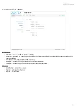
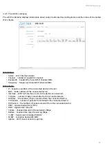
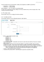
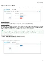
4.10.2  The «Configuration» submenu

In the «Configuration» submenu, the current configuration is saved to a file and the configuration is downloaded to 
the device.

Backup Configuration

To save current device configuration to local computer click on the 'Download' button.

Restore Configuration

To download the configuration file saved on the local computer, use the 

Restore Configuration

 item. To update the 

device configuration click the 'Choose file' button, specify a file (in .tar.gz format) and click the 'Upload File' button. 
Uploaded configuration will be applied automatically and does not require device reboot.

Reset to Default Configuration

To reset all the settings to default values, press «Reset» button.

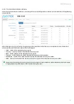
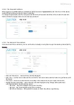
4.10.3  The «Reboot» submenu

To reboot the device, click on the «Reboot» button.

Note that all the passwords of configuration are encrypted with a key depending on device MAC address. 
When uploading a configuration from one device to another, you first need to reset the passwords, or 
change them in the configuration file before downloading to the device (encrypted fields).

Summary of Contents for WB-15-W

Page 1: ...IP address 192 168 1 1 Username admin Password password Wireless access point WB 15 W User manual Firmware version 1 1 0 ...

Page 2: ...B 15 W mounting 12 3 3 1 Pre tuning 12 4 Managing the device through web interface 16 4 1 Getting started 16 4 2 Applying configuration and discarding changes 17 4 3 Main elements of the web interface 17 4 4 The Monitoring menu 18 4 4 1 The Device Information submenu 18 4 4 2 The Network Information submenu 19 4 4 3 The Mobile network submenu 20 4 4 4 The Interfaces submenu 22 4 4 5 The Wi Fi subm...

Page 3: ...8 3 The Advanced submenu 32 4 9 The VAP menu 33 4 9 1 The Summary submenu 33 4 9 2 The VAP submenu 34 4 10 The System menu 35 4 10 1 The Device Firmware Upgrade submenu 35 4 10 2 The Configuration submenu 36 4 10 3 The Reboot submenu 36 4 10 4 The Password submenu 37 4 10 5 The Date and Time submenu 37 5 Configuration example 39 6 The list of changes 42 ...

Page 4: ... base station traffic shaping This manual specifies intended purpose main technical parameters design installation procedure safe operation rules and installation recommendations and also specifies settings that available in WEB interface of the device 1 2 Symbols Notes and warnings Notes contain important information tips or recommendations on device operation and setup Warnings inform users abou...

Page 5: ...3G 4G antennas Omni sector panel etc 1 SMA female connector for connecting external GPS antenna Wi Fi 2 4 GHz IEEE 802 11b g n Device is powered through a 24V PoE injector from a 220V network or through a DC power adapter Functions WLAN capabilities Support for IEEE 802 11b g n Data aggregation including A MPDU Tx Rx and A MSDU Rx WMM based priorities and packet planning Support for hidden SSID Su...

Page 6: ...thenet interface Number of ports 1 Electrical connector RJ 45 Data rate Mbps 10 100 Standards BASE T 2G 3G 4G interface parameters Frequency ranges 4G LTE FDD B1 B3 B5 B7 B8 B20 4G LTE TDD B40 3G UMTS B1 B8 2G GSM 850M 900M 1800M 1900M Data transfer rate1 4G LTE FDD Cat 4 150 Mbps DL 50 Mbps UL 4G LTE TDD Cat 4 130 Mbps DL 35 Mbps UL 3G DC HSPA 42 Mbps DL 5 76 Mbps UL 2G EDGE 384 Kbps DL 384 Kbps ...

Page 7: ...g n 1 13 2412 2472 MHz Data transfer rate1 Mbps 802 11n up to 300 Mbps Maximym transmitter output power2 2 4 GHz up to 18 dBm Receiver sensitivity 2 4 GHz up to 90 dBm Security 64 128 152 bit WEP encryption of the data WPA WPA2 data encryption Control Remote control WEB Telnet SSH General parameters Processor Realtek RTL8197FS RAM 128 MB Flash 32 MB Power supply Passive PoE 24 V DC 9 36 V Power co...

Page 8: ... coverage range 2 The value of the maximum output power will vary according to the rules of radio frequency regulation in your country 2 4 Design WB 15 W housed in a plastic case industrial version The size of the device 88x232 5x47 mm The layout of WB 15 W is shown in the figure below Under the cover at the bottom of the device are located factory reset button F slot for installing two 2G 3G 4G n...

Page 9: ...r description is shown in the table below LED LED state Description Power Device power and operation status LED solid green the device power supply is enabled connected to the mobile network normal operation solid orange the device is not connected to the mobile network solid red device starts up LAN Ethernet interface port indicator solid green the channel between Ethernet interface of WB 12 W an...

Page 10: ...green at least one VAP is enabled on the device Link level indicators from a cellular provider base station RSSI solid red the signal level is less than 81 dBm solid yellow the signal level is less than 69 dBm solid green the signal level is more or equal to 69 dBm none of the indicators is on no signal the device is not connected to the mobile network 2 6 The device schematic structure ...

Page 11: ...rebooted automatically DHCP server will be launched by default clients connected via Ethernet will receive address in the range from 192 168 1 2 to 192 168 1 254 with subnet mask 255 255 255 0 The device address is 192 168 1 1 24 User Name Password to access via Web interface admin password 2 8 Delivery Package The WB 15 W standard delivery package includes WB 15 W access point Mounting kit Operat...

Page 12: ...and enable device check the device for visible mechanical defects If defects are observed you should stop the device installation draw up corresponding act and contact the supplier Install the device on communications mast pole wall in the way that the Ethernet port is pointed down During the device installation to provide Wi Fi coverage area with the best characteristics take into account the fol...

Page 13: ...nting algorithm Attach the bracket to the device with the screws provided as shown in the figure below Install the device on communications mast pole pointing Ethernet port down as it is shown on the figure below Attach the device using clamps supplied in the device package Comply the safety rules and recommendations given in Safety rules and Installation recommendations Please note that for the d...

Page 14: ...14 3 4 Remove the bottom cover which close bottom panel and connect the Ethernet cable to the PoE port If the device will be supplied by a DC network connect the contacts of the DC power supply 9 36V observing the polarity ...

Page 15: ...t it faces toward the base station Connect Ethernet cable of your WB 15 W to LAN port of PoE injector Passive PoE 24V If the device is connected to a DC power supply if you need to connect to the switch make sure that PoE is disabled on it If you using PoE injector connect it to 220 V power supply network using the cable To avoid damage to the device it is recommended to use lightning protection ...

Page 16: ...ed on a browser window 3 Enter your username into Login and password into Password field 4 Click the Log in button A menu for monitoring the status of the device will open in a browser window 5 If necessary you can switch the information display language Russian and English languages are available for WEB interface Factory default IP address 192 168 1 1 subnet mask 255 255 255 0 DHCP server is lau...

Page 17: ...es 4 3 Main elements of the web interface Navigation elements of the WEB interface are shown on the figure below User interface window is divided into five general areas Menu tabs categorize the submenu tabs Monitoring Mobile Network LAN Radio VAP System Interface language selection and Logout button designed to to end a session in the web interface under a given user After clicking the button the...

Page 18: ... The Device Information submenu displays main WB 15 W parameters Product device model name Hardware Version device hardware version Factory MAC Address device MAC address set by manufacturer Serial Number device serial number setted by manufacturer Software Version device firmware version Firmware Backup Version previously installed firmware version Boot Version device bootloader firmware version ...

Page 19: ...etween the IP and MAC addresses of neighboring network devices IP address device IP address MAC device MAC address Routes Interface device interface name Destination IP address of destination host or subnet that the route is established to Gateway gateway IP address that allows for the access to the Destination Netmask subnet mask Flags certain route characteristics The following flag values exist...

Page 20: ... points to a buffered route to which an entry in the ARP table corresponds C means that the route source is the core routing buffer L indicates that the destination of the route is one of the addresses of this computer Such local routes exist in the routing buffer only B means that the route destination is a broadcasting address Such broadcast routes exist in the routing buffer only I indicates th...

Page 21: ...SRP level of received signal from the base station for LTE standard RSRQ quality level of received pilot signals for LTE standard SINR ratio of the useful signal level to the noise level at the receiving point for LTE standard Channel redundancy Status operation status Not configured the parameter is disabled in the device configuration Active channel redundancy is enabled Changing the active SIM ...

Page 22: ...ng an IP address on the WAN interface for network communication with the internal modem IP address IP address of the WAN interface RX Bytes amount of traffic received on the WAN interface TX Bytes amount of traffic transmitted from the WAN interface Ethernet Link Status current link status Speed set speed on the link Duplex used mode ...

Page 23: ...st MAC MAC address of the connected device Interface WB 15 W interface to which the device is connected TX Bytes number of bytes transmitted to the connected device RX Bytes the number of bytes received from the connected device TX Packets number of packets transmitted to the connected device RX Packets the number of packets received from the connected device RSSI received signal level dBm SNR sig...

Page 24: ...pear SSID SSID of the detected access point Security security mode of the detected access point MAC MAC address of the detected access point Channel radio channel on which the detected access point operates Bandwidth width of the radio channel used by the detected access point MHz RSSI the level with which the device receives the signal of the detected access point dBm Please note that during the ...

Page 25: ...fault Also you can choose 2G 3G 4G 2G 3G 2G 4G 3G 4G When choosing the double option the connection preference will be given to a more modern standard for example when the 3G 4G mode is set then 4G connection will be priority SIM Card selects an active SIM card to connect to a mobile network The default value is SIM1 that is a SIM card that is located in SIM slot 1 APN Auto auto detection of APN f...

Page 26: ...een received at all this ICMP request is considered unanswered ICMP Echo Request Count number of consecutive ICMP requests sent each time the procedure starts after the time period for sending ICMP requests The decision to switch the SIM card is based on the statistics obtained as a result of the procedure DSCP priority of sent ICMP requests Ping server 1 Ping server 2 Ping server 3 servers to whi...

Page 27: ...e device in the LAN subnet Mask mask of the device s LAN subnet and DHCP server which issues addresses to clients connected to Wi Fi or Ethernet DHCP server settings Enable set the flag so that clients connected to Wi Fi or Ethernet interfaces can get an IP address Specify the following parameters for the DHCP server Please note that switching the active SIM card or moving to the next ping server ...

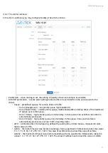
Page 28: ...onnecting to the Wi Fi or Ethernet interfaces of the device the client with the specified MAC address will be given the specified IP address 4 7 1 The Access submenu In the Access submenu you can configure access to the device via the web interface Telnet SSH NETCONF and SNMP To enable access to the device via the web interface via HTTP protocol set the flag next to WEB In the window that appears ...

Page 29: ...ings submenu you can configure settings of SNMP agent The device supports SNMPv1 SNMPv2 SNMPv3 To change the SNMP settings check the box next to SNMP apply the configuration and then go to the SNMP submenu roCommunity a password to read the parameters by default public rwCommunity a password to configure write parameters by default private TrapSink IP address or domain name of SNMPv1 trap message ...

Page 30: ...EE 802 11b IEEE 802 11g IEEE 802 11n IEEE 802 11b g IEEE 802 11b g n Channel Bandwidth MHz bandwidth of the channel on which the radio interface of the device operates takes values 20 40 Primary Channel primary channel of the radio interface The setting is available when you select a bandwidth of 40 MHz in this case the total channel of 40 MHz is formed from two adjacent frequency channels of 20 M...

Page 31: ...e Data 1 Video high priority queue minimal delay In this queue time sensitive video data is automatically processed Data 0 Voice high priority queue minimal delay In this queue time sensitive data is automatically processed such as VoIP streaming video AIFS Arbitration Inter Frame Spacing defines the waiting time of data frames measured in slots takes values 1 255 cwMin the initial timeout value b...

Page 32: ...Short Guard interval Access point transmits data using 400 ns Guard interval instead of 800 ns to clients which also support Short GI STBC Soace Time Block Coding method dedicated to improve data transmission reliability The field is available only if the selected mode of operation of the radio interface includes 802 11n When checked the device transmits one data flow through several antennas When...

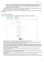
Page 33: ... for 802 11n standard 4 9 The VAP menu In the VAP menu you configure virtual Wi Fi access points VAP 4 9 1 The Summary submenu The Summary submenu displays the settings of all virtual Wi Fi APs VAP You can see the settings of each virtual AP in sections VAP0 3 VAP0 3 the sequence number of the virtual access point Enabled when the flag is set VAP is enabled otherwise it is disabled Security Mode t...

Page 34: ...methods the following setting will be available WPA Key key password required to connect to the virtual access point The key length is from 8 to 63 symbols Shapers Show display configuration field VAP Limit Down restriction of bandwidth in the direction from the access point to the clients in total connected to this VAP Kbps VAP Limit Up restriction of bandwidth in the direction from the clients i...

Page 35: ...that allows you to make a backup version of the firmware active this will require a reboot of the device The active firmware version will not be set as a backup Firmware update Download the firmware file from https eltex co com support downloads and save it on your computer To do this click the Choose file button in the Firmware Image field and specify the path to the firmware file in tar gz forma...

Page 36: ...n click the Choose file button specify a file in tar gz format and click the Upload File button Uploaded configuration will be applied automatically and does not require device reboot Reset to Default Configuration To reset all the settings to default values press Reset button 4 10 3 The Reboot submenu To reboot the device click on the Reboot button Note that all the passwords of configuration are...

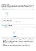
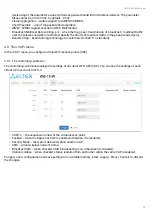
Page 37: ... time manually or using the time synchronization protocol NTP Manual Date and Time device date and time currently displayed Date Time set the current date and time or click the Set current date and time button to synchronize with the device Time Zone allows to set the timezone according to the nearest city for your region from the list Daylight Saving Time Enable when selected automatic daylight s...

Page 38: ... Server time synchronization server IP address domain name Time Zone allows to set the timezone according to the nearest city for your region from the list To apply a new configuration and store settings into the non volatile memory click the Apply button To discard changes click Cancel button ...

Page 39: ...the filds and press Log in By default login admin password password If the window is not displayed make sure that the PC and the device are in the same subnet After connecting the device to the mobile network 1 2 minutes after loading the device if there is a SIM card in the SIM1 slot the Monitoring Mobile Network menu will display information about the network connection mode mobile network opera...

Page 40: ...VAP settings go to the VAP menu To save and apply changes click In the VAP menu go to one of the four VAPs turn it on configure the settings necessary for connecting clients SSID security mode security key restriction of connected clients After completing the configuration clients will be able to connect to VAP and gain access to the Internet To save and apply changes click ...

Page 41: ...15 W User manual 41 7 To prevent unauthorized access to the device after making the settings go to the System menu and in the Password tab change the default password value To save and apply changes click ...

Page 42: ...WB 15 W User manual 42 6 The list of changes Document Version Issue Date Revisions Version 1 0 12 12 2018 First issue Firmware version 1 1 0 ...

Page 43: ...sibirsk Russian Federation 630020 E mail techsupp eltex co ru You are welcome to visit ELTEX official website to get the relevant technical documentation and software for ELTEX products or consult a Service Center Specialist on our technical forum https eltex co com https eltex co com support downloads http forum eltex co ru ...

Reviews: