background image

86500021


Bedienungsanleitung / Operating Instructions  

ELTC-41/ELTC-42 


Autor 

Peter Schmidt 

Revision 3 

11.07.2017 


 9/ 13 

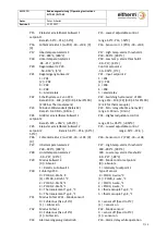
2.8


ModBus-Schnittstelle / ModBus-Interface 

Type:   

RS485 (Physical Layer)  Baudrate: 


max. 38400 Baud 

Protokoll: 

N,8,2 / ModBus  

Anzahl d. Geräte / number of units: 

max. 32 


2.9


ModBus Parameter / ModBus Parameter 


Bit 0…15 

Zustand Ausgänge 


output states 


Alarmverzögerung: Temperaturlimits 

überschritten, Parameter P33 aktiv. 

Alarm delay: Temperature limits 

exceeded, parameter P33 active. 


Bit 16…31 

Fehlermeldungen 


error codes 


ModBus: 

Read discrete inputs   

Read device ID 


Function = 0x02 


Function = 0x2B 

Object ID 00:  eltherm GmbH 


Address = 0 


Address = 0x0E Object ID 01:  ELTC-41/42 


QTY = 16 


ID Code = 0x01 Object ID 02:  Rev03, Bxxx 


Object ID = 0x00 


ModBus: 

Read input register 


Function = 0x04 

HiByte   

Hardware ID:  41 

(for ELTC-

41/42) 


Address = 0 


LowByte 

Param.-list ID:  3 

(for version 03) 


Allgemein / General 


Auflösung Temp.-werte 1K / all temperature values are with resolution 1K 


Communication setting is N,8,2 (None parity, 8 data bits, 2 stop bit) 


2.10


Modus Alarmrelais / 

Alarm Relay Mode


Liegt beim Gerätestart die Isttemperatur unterhalb von P18 (P28), wird als Alarmverzögerung 

einmalig P34 verwendet, um der Anlage mehr Zeit zu gewähren. Im normalen Betrieb wird P33 

als Alarmverzögerung verwendet. 

If, with power-on, the actual temperature is located below P18 (P28), P34 will be used as alarm 

delay to grant more time for the equipment. During normal operation, P33 is used as alarm 

delay parameter. 

Bit 0 

Bit 1 

Bit 2 

Bit 3 

LED relay 1 

LED relay 2


LED 3


LED Alarm


Bit 4 

Bit 5 

Bit 6 

Bit 7 

Relay 1 

Relay 2 

Remote SP1 

Bit 8 

Bit 9 

Bit 10 

Bit 11 

Alarm Fühler1 

Probe1 alarm 

Alarmverz. Fühler1 

Alarm delay probe1


Alarm Fühler2 

Probe2 alarm 

Alarmverz. Fühler2 

Alarm 

delay probe2


Bit 12 

Bit 13 

Bit 14 

Bit 15 

Bit 16 

Bit 17 

Bit 18 

Bit 19 

Kurzschluss Fühler1 

Probe1 short 

Unterbrechung Fühler1 

Probe 1 open


Fühler1 3-Leiter 

Probe1 3-wire 

Kurzschluss Fühler2 

Probe2 short


Bit 20 

Bit 21 

Bit 22 

Bit 23 

Unterbrechung Fühler2  

Probe 2 open


Fühler2 3-Leiter 

Probe2 3-wire


Fehler Spannung 

Fault voltage


Fehler Strom 

Fault current


Bit 24 

Bit 25 

Bit 26 

Bit 27 

Bit 28 

Bit 29 

Bit 30 

Bit 31 

Fehler int.Temperatur 

Fault int. temperature


Fehler Referenzspg. 

Fault ref.-voltage


Interner Fehler 

Internal fault


Summary of Contents for 0620041

Page 1: ...er ELTC 41 Art Nr Part No 0620041 ELTC 42 Art Nr Part No 0620042 eltherm GmbH Ernst Heinkel Str 6 10 57299 Burbach T 49 2736 4413 0 F 49 2736 4413 50 info eltherm com 86500021 BU 106 Bedienungsanleitung für Operating Manual ELTC 41 ELTC 42 Autor Peter Schmidt Revision 3 11 07 2017 ...

Page 2: ...Mode 9 3 Technische Daten Technical Data 10 4 Installations Sicherheitshinweise Installation Safety Insturctions 11 5 Abmessungen Dimensions 12 6 Anschluss Connection 12 7 Lieferumfang Parts included 13 8 RTEW 13 Bitte Sicherheitshinweise beachten Please Note Safety Instructions Vor Inbetriebnahme Betriebsanleitung sorgfältig lesen Entstehen durch Nichtbeachtung Schäden erlöschen die Garantieanspr...

Page 3: ...Bei Sensorfehlern schaltet das Steuerrelais abhängig von der Konfiguration des Reglers die Heizleitung aus bzw ein If the actual temperature P01 falls below the control set point P10 minus hysteresis P12 the power relay K1 switches the heating ON The integrated alarm relay K2 allows to forward error messages with occurring under over temperature sensor break or short circuit While sensor malfuncti...

Page 4: ...overtemperature protection with sliding set point 2 dependent of set point 1 Load to be switched by separate contactor P11 1 P21 2 P29 1 input F1 linked to K1 input F2 linked to K2 2 Bedienung Operation Die Bedienung gestaltet sich sehr einfach Nach dem Einschalten erscheinen die Typennummern des Gerätes C41 und C42 und nach ca drei Sekunden der gemessene Istwert Bei kurzem Drücken der Taste P ers...

Page 5: ... Code benötigt zeigt das Display C00 Sie stellen mit den Pfeiltasten die nötige Codenummer ein 42 und bestätigen mit P Nach ca 1 Min ohne Tastendruck wird der Code erneut angefordert The control set points can always be changed within the limits set by P14 P15 resp P24 P25 All other parameters are protected by a code If a code is necessary the display shows C00 Now set the value to 42 and confirm ...

Page 6: ... AL2 Über Untertemperatur Eingang 2 over undertemperature sensor 2 2 7 Parameter und deren Bedeutung Parameter Explanation P01 Istwert am Temperatursensor 1 nur Anz P01 Actual sensor 1 temp disp only P02 Istwert am Temperatursensor 2 nur Anz P02 Actual sensor 2 temp disp only P03 Istwert Spannungseingang 0 10 V nur Anz P03 Actual voltage input 0 10V disp only P04 Istwert Stromeingang 4 20 mA nur A...

Page 7: ... P24 Größter einstellbarer Sollwert 2 P24 Highest adjustable control setpoint2 Bereich P25 950 C 950 C range P25 950 C 950 C P25 Kleinster einstellbarer Sollwert 2 P25 Lowest adjustable control setpoint2 Bereich 50 C P24 50 C range 50 C P24 50 C P26 Fühlerkorrektur 2 zu P02 30 10K 0 P26 Sensor corr 2 P02 30 10K 0 P27 Übertemperaturalarm 2 P27 High temp alarm threshold 2 P28 999 C 999 C P28 999 C 9...

Page 8: ... Werte AC Einweggleichrichtung values AC half cycle rectifier 3 Sollw vorgabe Sollwert 1 0 10V Eingang 3 setpoint setting 1 0 10V input wird ersetzt durch P03 will be replaced by P03 P41 Anzeige bei 0V P41 Indication at 0V 99 999 0 99 999 0 P42 Anzeige bei 10V P42 Indication at 10V 99 999 100 99 999 100 P50 Modus Stromeingang P50 Mode current input 0 Aus P04 wird auf den Wert von P51 gesetzt 0 off...

Page 9: ...s Alarmrelais Alarm Relay Mode Liegt beim Gerätestart die Isttemperatur unterhalb von P18 P28 wird als Alarmverzögerung einmalig P34 verwendet um der Anlage mehr Zeit zu gewähren Im normalen Betrieb wird P33 als Alarmverzögerung verwendet If with power on the actual temperature is located below P18 P28 P34 will be used as alarm delay to grant more time for the equipment During normal operation P33...

Page 10: ...ay Relaisanzeige 3 stellig LED rot 11 0mm 2 0 mm rot Anschlussklemmen Schraubklemmen X1 X2 max 2 5mm X3 X7 max 1 5mm Kupferleitung Abisolierlänge 8mm Schutzart Front Gehäuse IP 54 IP 00 Controller type ELTC 41 ELTC 42 nominal voltage 100 240VAC 10 50 60 Hz 24VDC 10 or 22 28VAC power consumption max 5 W max 100mA temperature probe 2 PT100 2 3 wire or 2 thermocouples type K relay K1 12A res resp AC1...

Page 11: ...em Niederschlag und Sonneneinstrahlung geschützt sind Mounting location is to be chosen in compliance with the IP rating Preferredmounting locations offer protection against precipitation and direct sunlight Die Fühlerleitungen müssen bei Verlängerung abgeschirmt sein die Abschirmung ist einseitig nahe des Reglers zu erden Die Leitung darf nicht parallel zu netzspannungsführenden Leitungen verlegt...

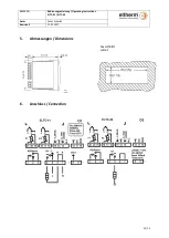
Page 12: ...86500021 Bedienungsanleitung Operating Instructions ELTC 41 ELTC 42 Autor Peter Schmidt Revision 3 11 07 2017 12 13 5 Abmessungen Dimensions Aussschnitt cutout 6 Anschluss Connection ...

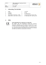
Page 13: ...ecker 3 5mm Raster codiert 5 mating plugs 3 5mm spacing coded 8 RTEW Konformitätserklärung Declaration of conformity Wir erklären dass das beschriebene Produkt die Richtlinien 2014 35 EU 2014 30 EU und 2011 65 EU voll erfüllt Wenn Sie eine detaillierte Konformitätserklärung benötigen sprechen Sie uns bitte an We declare that the described product is in full compliance with the directives 2014 35 E...

Reviews: