5
DMX Charts
3 channel mode:
DMX-512:
• DMX (Digital Multiplex) is a universal protocol used as a form of communication between intelligent fixtures
and controllers. A DMX controller sends DMX data instructions form the controller to the fixture. DMX data is
sent as serial data that travels from fixture to fixture via the DATA “IN” and DATA “OUT” XLR terminals located
on all DMX fixtures (most controllers only have a data “out” terminal).
DMX Linking:
• DMX is a language allowing all makes and models of different manufactures to be linked together and operate
from a single controller, as long as all fixtures and the controller are DMX compliant. To ensure proper DMX data
transmission, when using several DMX fixtures try to use the shortest cable path possible. The order in which
fixtures are connected in a DMX line does not influence the DMX addressing. For example; a fixture assigned
to a DMX address of 1 may be placed anywhere in a DMX line, at the beginning, at the end, or anywhere in the
middle. When a fixture is assigned a DMX address of 1, the DMX controller knows to send DATA assigned to
address 1 to that unit, no matter where it is located in the DMX chain.
DATA Cable (DMX cable) requirements (for DMX operation):
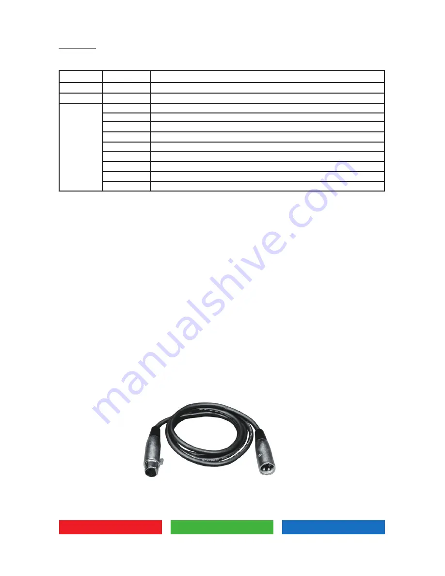
• The LED Zoom can be controlled via DMX-512 protocol. The DMX address is set on the back of the unit. Your
unit and your DMX controller require a standard 3-pin or 5-pin XLR connector for data input/output (figure 1).
Figure 1
Also remember that DMX cable must be daisy chained and cannot be split.
Channel
Value
0-255
0-255
0-15
16-45
46-75
76-105
106-135
136-165
166-195
196-225
226-255
CH1
CH2
CH3
Function
Dimming 0-100%
Strobe speed (slow to fast)
Dimmer curve and response select on fixture
Dimmer curve Linear response halogen
Dimmer curve Square response halogen
Dimmer curve Inverse Square response halogen
Dimmer curve S response halogen
Dimmer curve Linear response LED
Dimmer curve Square response LED
Dimmer curve Inverse Square response LED
Dimmer curve S response LED


