background image

12

te 2teilige Sicherheitscode des Ventilantriebes). 

•  Im Anschluss erfolgt ein Signalton sowie die Anzeige „A1”.

•  Der Ventilantrieb fährt jetzt den Steuerstift ganz zurück, 

um die Montage zu erleichtern. 

•  Anschließend erscheint in der Anzeige „A2”.

3.2.3 Montage des Ventil-

antriebs am Heizkörper

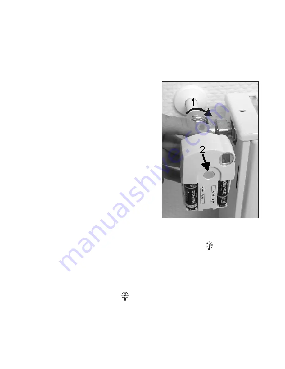
•  Schrauben  Sie  den  Ventil-

antrieb durch Drehen der Über­

wurfmutter  von  Hand  fest  auf 

das Ventil (1). Bei Ventilen der 

Firma  Danfoss  montieren  Sie 

zuvor  einen  der  beiliegenden 

Adapter  auf  das  Ventil.  Die 

Abbildungen auf S. 13 zeigen, 

welcher  Adapter  zu  welchem 

Ventil gehört. 

•  Betätigen Sie die Taste am Ven­

tilantrieb einmal kurz (2). 

•  Das Display zeigt „A3” und der 

Ventilantrieb schließt das Ventil. 

•  Anschließend  blinkt  das  Antennensymbol    im  Display 

und das Display zeigt „0%” an. 

•  Setzen Sie den Batteriefachdeckel auf. 

•  Der Ventilantrieb bestätigt das erste empfangene Funk­

protokoll mit einem Signalton.

•  Das Antennensymbol   ist jetzt dauerhaft aktiv. 

•  Damit ist die Installation abgeschlossen und die vorpro­

grammierten Einstellungen können den individuellen Be­

dürfnissen angepasst werden.

Summary of Contents for FHT8-Set

Page 1: ...1 FHT8 Set Funk Heizkörperthermostat Komplettset S 1 Heating control set P 38 Bedienungsanleitung User manual ELV Elektronik AG PF 1000 D 26787 Leer Telefon 0491 6008 88 Telefax 0491 6008 244 ...

Page 2: ...rarbeitet werden Es ist möglich daß das vorliegende Handbuch noch druck tech nische Mängel oder Druckfehler aufweist Die Angaben in diesem Handbuch werden jedoch regelmäßig überprüft und Korrekturen in der nächsten Ausgabe vorgenommen Für Fehler technischer oder drucktechnischer Art und ihre Folgen übernehmen wir keine Haftung Alle Warenzeichen und Schutzrechte werden anerkannt Printed in Hong Kon...

Page 3: ...tems 13 4 1 Einstellen der Komforttemperatur und der Absenktemperatur 14 4 2 Das Wochenprofil gestalten 15 4 3 Betriebsarten 17 4 4 Tastensperre 19 4 5 Wechsel zwischen Komfort und Absenktemperatur 19 4 6 Heizpause 19 4 7 Schließen des Ventils 20 4 8 Notbetrieb des Ventilantriebes 21 4 9 Sonderfunktionen 21 5 Batteriewechsel 31 5 1 Regeleinheit 31 5 2 Ventilantrieb 32 6 Problembehebung 34 6 1 Fehl...

Page 4: ... bietet zahlreiche Vorteile gegenüber einfachen mechanischen Thermostaten Durch die Aufteilung in den oder die am Heizkörper mon tierte Ventilantriebe FHT 8V und die an der Wand ange brachte Bedien und Regeleinheit FHT 8R sind Einstel lungen sehr komfortabel durchführbar Das an die Lebensgewohnheiten anpassbare Zeitpro gramm ermöglicht es dass der Raum stets angenehm warm ist wenn er genutzt wird ...

Page 5: ...ehrere Funk Heizkörperthermostat Systeme unabhängig voneinander in einem Haushalt betreiben zu kön nen ist das Funksignal mit einem zweiteiligen Sicherheits code versehen Jeder Teil umfasst 100 verschiedene Ein stellmöglichkeiten sodass insgesamt 10000 verschiedene Sicherheitscodes zur Verfügung stehen Damit die Regel einheit und der die Ventilantriebe miteinander kommunizie ren können muss bei al...

Page 6: ...rößer sein kann Beeinträchtigungen für empfindliche Menschen und Tiere sind somit nicht zu erwarten Reinigen Sie das Gerät nur mit einem trockenen Leinen tuch das bei starken Verschmutzungen leicht angefeuch tet sein darf Verwenden Sie zur Reinigung keine löse mittelhaltigen Reinigungsmittel Achten Sie darauf dass keine Feuchtigkeit in das Geräteinnere gelangt Das Aufheizen eines Raumes benötigt a...

Page 7: ...t erworben werden 2 Sicherheitshinweise Die Geräte sind keine Spielzeuge erlauben Sie Kindern nicht damit zu spielen Verpackungsmaterial nicht achtlos liegen lassen dies kann für Kinder zu einem gefährlichen Spielzeug werden Öffnen Sie das Gerät nicht es enthält keine durch den Anwender zu wartenden Teile Im Fehlerfall schicken Sie das Gerät an den Service 3 Installation des Systems 3 1 Anbringen ...

Page 8: ...nd lotrecht an die Wand Markieren Sie durch die beiden Langlöcher die Position der Boh rungen Entfernen Sie den Wandhalter und bohren Sie an den Markierungen ausreichend tief mit einem 6 mm Bohrer Achten Sie hierbei darauf dass keine Leitungen etc ange bohrt werden Versehen Sie die Bohrlöcher mit den beiliegenden Dübeln und montieren Sie den Wandhalter mit Hilfe der ebenfalls beiliegenden Schraube...

Page 9: ... dem Stellrad das Jahr ein und bestätigen Sie mit der Taste PROG Einstellung Monat Es erscheint folgende Anzeige MO DI MI DO FR SA SO 0 6 12 18 24 Stellen Sie mit dem Stellrad den Monat ein und bestätigen Sie mit der Taste PROG Einstellung Tag Es erscheint folgende Anzeige MO DI MI DO FR SA SO 0 6 12 18 24 Stellen Sie mit dem Stellrad den Tag ein und bestätigen Sie mit der Taste PROG Einstellung U...

Page 10: ...DO FR SA SO 0 6 12 18 24 Stellen Sie mit dem Stellrad die Minuten ein Bestätigen Sie mit der Taste PROG Anschließend zeigt das Dis play Sync und 120 an Jetzt zählt die Regeleinheit im 1Sekunden Takt herunter und befindet sich nach Ablauf von 120 Sekunden im normalen Be triebsmodus Schieben Sie die Regeleinheit von oben bis zum Einrasten auf die Wandhalterung ...

Page 11: ...egen der Batterien in den Ventilantrieb Entfernen Sie den Batterie fachdeckel des Ventilantriebes durch Schieben nach unten Setzen Sie die Batterien in das Batteriefach ein Achtung Bitte unbedingt die dargestellte Po larität beachten da die Elektro nik sonst evtl zerstört wird Das Display zeigt C1 und an schließend eine 2stellige Zahl daraufhin C2 und erneut eine 2stellige Zahl die beiden Zah len ...

Page 12: ... zuvor einen der beiliegenden Adapter auf das Ventil Die Abbildungen auf S 13 zeigen welcher Adapter zu welchem Ventil gehört Betätigen Sie die Taste am Ven tilantrieb einmal kurz 2 Das Display zeigt A3 und der Ventilantrieb schließt das Ventil Anschließend blinkt das Antennensymbol im Display und das Display zeigt 0 an Setzen Sie den Batteriefachdeckel auf Der Ventilantrieb bestätigt das erste em...

Page 13: ...des Systems Werkseitig sind bereits alle erforderlichen Einstellungen des Systems mit einem Standardprogramm vorbelegt Heizphase Komforttemperatur 21 C von 6 00 Uhr bis 23 00 Uhr Absenkphase Absenktemperatur 17 C von 23 00 bis 6 00 RAVL RAV RA Die Adapter für die Ventile Typ RAV und RA sind nach dem Aufrasten auf den Ventilkörper mit der beiliegenden Schrau be und Mutter zu befestigen Auf Ventile ...

Page 14: ...tiger Wechsel zwischen Absenk und Komforttemperatur so wird auf der unteren Skala des Displays durch einen Balken dargestellt wann im Laufe des Tages auf Komforttempera tur geregelt wird Ein Sonnensymbol im Display symbolisiert dass die Komforttemperatur aktiv ist ein Mondsymbol zeigt an dass auf Absenktemperatur geregelt wird Komfort und die Absenktemperatur verändern Betätigen Sie die Taste läng...

Page 15: ...für den automatischen Wechsel zwischen Komfort und Absenktemperatur kann für jeden Wochen tag einzeln verändert und damit den persönlichen Lebens gewohnheiten angepasst werden Betätigen Sie die PROG Taste 1 mal kurz Es erscheint die Anzeige MO DI MI DO FR SA SO 0 6 12 18 24 Prog Wählen Sie mit dem Stellrad den Tag aus für den das Zeitprogramm verändert werden soll Es können sowohl die Wochentage e...

Page 16: ...emperatur geregelt werden soll Bestätigen Sie diesen durch Betätigen der PROG Taste Es erscheint in der Anzeige der erste Absenk Zeitpunkt MO DI MI DO FR SA SO 0 6 12 18 24 Prog Wählen Sie mit dem Stellrad den Zeitpunkt ab dem auf die Absenktemperatur geregelt werden soll Bestätigen Sie diesen durch Betätigen der PROG Taste Dieser Vorgang wiederholt sich für die 2 Komforttempe ratur Zeit und die 2...

Page 17: ... h wenn der Vortag mit Komforttemperatur beendet wird so setzt sich diese Heizphase ggf am nächsten Tag fort Während der Programmierung werden die Balken je doch nicht angezeigt 4 3 Betriebsarten Das Wechseln der Betriebsart erfolgt mit der Taste FUNK TION Durch wiederholtes Drücken sind dabei die verschie denen Modi nacheinander abrufbar 4 3 1 Automatikbetrieb Im Automatikbetrieb Anzeige Auto fol...

Page 18: ...nierten Zeitraum z B die Dau er einer Party oder eines Urlaubs auf einem festen Tempe raturwert Danach wechselt der Regler selbsttätig in den Auto matikmodus Nach Anwahl dieser Betriebsart Koffer Symbol im Display mit der Taste FUNKTION stellen Sie zunächst den Zeit raum ein Für die folgenden 24 Stunden ist eine Abstufung in 1 2 Stunden Schritten vorgesehen Partyfunktion Darü ber hinaus erfolgt di...

Page 19: ...LOC aus der Anzeige verschwindet MO DI MI DO FR SA SO Auto 0 6 12 18 24 4 5 Wechsel zwischen Komfort und Absenktemperatur Weicht die Nutzung eines Raumes vom eingestellten Zeitpro gramm ab so kann die Temperatur wie oben beschrieben mit dem Stellrad verändert werden Es ist jedoch ebenfalls möglich direkt zwischen der Komfort und der Absenk temperatur zu wechseln indem die Taste kurz ge drückt wird...

Page 20: ...t ist zu wählen wenn der Raum gar nicht geheizt werden soll Das Ventil wird geschlossen und verbleibt in dieser Stellung Nur bei Frostgefahr Temperatur unter 5 C wird das Ventil geöffnet Der wöchentliche Verkalkungsschutz wird weiterhin durch geführt Um das Ventil zu schließen wechseln Sie durch Betätigen der Taste FUNKTION in die Betriebsart Manu Drehen Sie das Stellrad so lange links herum bis O...

Page 21: ...nnzeichneten Zapfen Drehen Sie den Verstellstift im Uhrzeigersinn wärmer gegen den Uhrzeigersinn kälter 4 9 Sonderfunktionen Das Menü Sonderfunktionen enthält die unten aufgezähl ten Funktionen Das Menü der Sonderfunktionen wird über einen langen Tastendruck der PROG Taste aufgerufen Das Menü wird nach 30 Sekunden Inaktivität automatisch geschlossen 1 CALC Festlegen des Zeitpunktes der Entkalkungs...

Page 22: ... des Entkalkungszeitpunktes Einmal wöchentlich wird das Ventil vollständig geöffnet und geschlossen Dies verhindert dass sich das Ventil durch Ab lagerungen festsetzt Der Zeitpunkt an dem diese Entkal kungsfahrt durchgeführt wird kann durch die Sonderfunktion CALC verändert werden MO DI MI DO FR SA SO 0 6 12 18 24 Betätigen Sie die Taste PROG so lange bis Sond in der Anzeige erscheint WählenSiemit...

Page 23: ...ion C F aus Bestätigen Sie diese mit der PROG Taste Wählen Sie mit dem Stellrad C oder F aus Bestätigen Sie mit der PROG Taste 4 9 3 Einstellen von Datum und Uhrzeit Betätigen Sie die Taste PROG so lange bis Sond in der Anzeige erscheint Wählen Sie mit dem Stellrad die Sonderfunktion dAt aus Bestätigen Sie diese mit der PROG Taste Die weiteren Einstellungen sind wie in 3 1 3 Einlegen der Batterien...

Page 24: ...in zufälliger Sicherheits code zugeteilt so dass hier normalerweise keine Einstellung erforderlich ist Soll der Code verändert bzw neu übertragen werden gehen Sie wie folgt vor Betätigen Sie die Taste PROG so lange bis Sond in der Anzeige erscheint WählenSiemitdemStellraddieSonderfunktion CodE aus Bestätigen Sie diese mit der PROG Taste Es erscheint folgende Anzeige MO DI MI DO FR SA SO 0 6 12 18 ...

Page 25: ... ca 3 Sekun den bis 3 Signaltöne erklingen Der Ventilantrieb ist jetzt empfangsbereit und das Display zeigt AC Durch Drücken der PROG Taste an der Regeleinheit starten Sie die Übertragung des Codes Der Ventilantrieb quittiert den korrekten Empfang des Codes mit einer Tonfolge Setzen Sie den Batteriefachdeckel wieder auf Der erste Empfang des regulären Funksignals wird mit einem Signalton betstätig...

Page 26: ...n hat so ist bei diesem Ventilantrieb die Taste so lange zu Drücken bis das Display des Ventilantriebes AC anzeigt und er 3 Si gnaltöne ausgibt Jetzt lösen Sie die Codeübertragung durch Betätigen der PROG Taste an der Regeleinheit aus 4 9 5 An A Mit diesem Menüpunkt lässt sich die Anzahl der zu steu ernden Heizkörper Ventilantriebe verändern Bei der In stallation eines zusätzlichen Ventilantriebes...

Page 27: ...en Sie die Taste für ca 3 Sekunden bis 3 Signal töne erklingen Der Ventilantrieb ist jetzt empfangsbereit und das Display zeigt AC Durch Drücken der PROG Taste an der Regeleinheit starten Sie die Übertragung des Codes Der Ventilantrieb quittiert den korrekten Empfang des Codes mit einer Tonfolge Setzen Sie den Batteriefachdeckel wieder auf Der erste Empfang des regulären Funksignals wird mit einem...

Page 28: ...in der Anzeige erscheint WählenSie mit dem Stellrad die Sonderfunktion SynC aus Bestätigen Sie diese mit der PROG Taste Anschließend zeigt das Display Sync und 120 an Jetzt zählt die Regeleinheit im 1Sekunden Takt herunter und be findet sich nach Ablauf von 120 Sekunden im normalen Be triebsmodus 4 9 7 tESt Mit der Funktion tESt kann überprüft werden ob alle Ven tilantriebe das Funksignal korrekt ...

Page 29: ...lange bis Sond in der Anzeige erscheint Wählen Sie mit dem Stellrad die Sonderfunktion StEL aus Bestätigen Sie diese mit der PROG Taste Die Anzeige zeigt die Ventilöffnung in an Eine Betätigung der PROG Taste beendet diese Funktion 4 9 9 t An Im Anlieferzustand zeigt der FHT 8R rechts auf dem Display die Solltemperatur d h die Temperatur auf die der Reg ler den Raum erwärmt an Mit der Sonder funkt...

Page 30: ...t der PROG Taste 4 9 10 OFFS Werden mehrere Heizkörper von einem Regler gesteuert so ist es möglich dass diese ungleichmäßig stark heizen Die Ursache liegt hier in einem stark voneinander abweichenden Durchflussverhalten der Ventile bzw schlecht dimensio nierten Heizkörpern Das Problem lässt sich evtl beheben indem man einzelne Heizkörper mehr positiver Offset bzw weniger negativer Offset heizen l...

Page 31: ...ondern nur in der Zeit von 10 00 Uhr bis 11 00 Uhr von 17 00 bis 18 00 Uhr und von 21 00 Uhr bis 22 00 Uhr Nehmen Sie die Regeleinheit vom Wandhalter und öffnen Sie den Batteriefachdeckel durch Schieben nach unten Entfernen Sie die Batterien aus dem Batteriefach und ent sorgen Sie diese umweltgerecht Achtung Verbrauchte Batterien gehören nicht in den Hausmüll sondern können kostenlos in den örtlic...

Page 32: ...ndern können kostenlos in den örtlichen Batteriesammelstellen abgegeben werden Warten Sie bis alle Segmente des Displays erloschen sind Dies lässt sich durch Betätigen und Halten der Taste am Ventilantrieb beschleunigen Setzen Sie die Batterien in das Batteriefach im Ventilan trieb ein Achtung Bitte unbedingt die dargestellte Pola rität beachten da die Elektronik sonst evtl zerstört wird Das Displ...

Page 33: ...end blinkt das Antennensymbol im Display und das Display zeigt 0 an Das erste empfangene Funksignal wir mit einem Signalton bestätigt und das Antennensymbol ist dauerhaft aktiv Setzen Sie den Batteriefachdeckel auf ...

Page 34: ...tieren F2 im Display Stellbereich zu groß Ventil ist nicht geeignet Dauerhafter Stellbereich zu klein Ventilantrieb neu Signalton und montieren F3 im Display Ventil ist nicht geeignet Kein Funksymbol Ausfall der Funk Regeleinheit an einer im Display der verbindung durch anderen Stelle Ventilantrieb gibt Störungen anordnen jede Stunde eine Batterien der Batterien erneuern Tonfolge aus Das Regeleinh...

Page 35: ...er Art Der Abstand der Regeleinheit oder des Ventilantriebes zu leitenden Flächen oder Gegenständen auch zum mensch lichen Körper oder dem Erdboden beeinflusst die Strah lungscharakteristik und somit die Reichweite Breitbandstörungen in nichtländlichen Gebieten können den Signal Rauschabstand verkleinern wodurch sich die Reichweite verringert Geräte mit benachbarten Arbeitsfrequenzen können den Em...

Page 36: ...uchtigkeit neben baulichen Gegebenheiten eine wichtige Rolle Hiermit erklärt die die ELV Elektronik AG dass sich dieses Gerät in Übereinstimmung mit den grundlegenden Anforde rungen und den anderen relevanten Vorschriften der Richtlinie 1999 5 EG befindet Die vollständige Konformitätserklärung finden Sie unter www elv de 8 Entsorgungshinweis Gerät nicht im Hausmüll entsorgen Elektronische Geräte s...

Page 37: ...ensdauer ca 2 Jahre Temperaturbereich 6 C bis 30 C Max Anzahl der Schaltzeiten 4 pro Tag bzw 28 pro Woche FHT8V 2 Reichweite Freifeld bis 100 m Empfangsfrequenz 868 35 MHz Stromversorgung 2 Alkaline Mignon Batterien Batterielebensdauer ca 2 Jahre Das CE Zeichen ist ein Freiverkehrszeichen das sich ausschließlich an die Behörden wendet und keine Zusicherung von Eigenschaften beinhaltet ...

Page 38: ...ion in this handbook is regularly checked and corrections made in the next issue We accept no liability for technical mistakes or printing errors or their consequences All trademarks and patents are acknowledged Printed in Hong Kong Modifications due to technical improvements may be made without prior notification 91511 FHT8R 3 FHT8V 2 V1 0 These operating instructions belong with this product The...

Page 39: ...perature 53 b Setting changing the week profile 54 c Modes of operation 57 d Key lock for keys and selection wheel 59 e Switching between comfort temperature and lowering temperature 59 f Heating pause 60 g Closing the valve 60 h Emergency operation of the valve operating mechanism 61 10 Special functions 62 11 Replacing of batteries 73 a FHT8R heating control 73 b FHT8V valve operating mechanism ...

Page 40: ...HT8R heating control measures the room tempera ture by means of an integrated sensor and transmits the corresponding control data to the FHT8V valve operat ing mechanisms Any other use e g in cooling systems floor heating sys tems etc is not permitted and may lead to severe dam age 2 Scope of supply FHT8R heating control Wall mounting set for heating control screws dowels FHT8V valve operating mec...

Page 41: ...osing of heating valves is no longer re quired The system is equipped with an integrated calcification protection Once every week time can be set the valve operating mechanism opens and closes the valve to pre vent blocking of the valve by lime deposits a Operating principle In the FHT8R heating control the room temperature is measured and compared to the desired temperature set ei ther by means o...

Page 42: ...from other radiosystems and ensures that sev eral radio controlled radiator thermostat systems can be operated separately in a household Each part of the code comprises 100 setting options This means that there are 10 000 different safety codes available To ensure commu nication between the heating control and the valve operat ing mechanism s the same safety code has to be set for all devices in a...

Page 43: ... weak radio signals These radio signals could however lead to malfunctions in life supporting systems The same may possibly apply to other areas The product must only be used in dry indoor areas it must be protected from moist and water The product is not a toy and must be kept out of the reach of children For safety and licensing CE reasons unauthorised con version of and or modifications to the ...

Page 44: ...umulators and do not throw batteries accumulators into a fire There is a risk of explosion Do not disassemble batteries accumulators Do not recharge normal batteries There is a risk of explo sion In case of longer periods of non use e g during stor age remove the inserted batteries accumulators to avoid damage by a leaking battery accumulator 5 Inserting the batteries into the FHT8R heating contro...

Page 45: ...the battery symbol is displayed on the LC dis play the battery voltage is low and the batteries should be replaced as soon as possible The same applies if the radio range decreases or if data are no longer displayed on the LC display 6 Wall mounting of FHT8R a Choosing an appropriate mounting location Make sure to choose an appropriate location for mounting the FHT8R heating control This has to me...

Page 46: ... the positions of the bores through the two slotted holes Depending on the type of wall drill two 6 mm holes and insert suitable dowels When drilling the bores and tightening the screws make sure not to damage any power lines or gas or water pipes etc Fix the wall holder using e g the enclosed screws Pay at tention that the two recessed slotted holes for the screws point in your direction If not a...

Page 47: ...et the year the month the day the hours and the minutes on the heating control Use the selection wheel to change the displayed values To confirm your selection briefly press the PROG key After inserting the batteries the year is displayed M O DI M I DO F R S A S O 0 6 1 2 1 8 2 4 P r o g Use the selection wheel to set the desired year To confirm your setting briefly press the PROG key The month is...

Page 48: ...essing the PROG key The hours are displayed MO DI MI DO FR SA SO 0 6 12 18 24 Use the selection wheel to set the desired hour and confirm your setting by pressing the PROG key The minutes are displayed MO DI MI DO FR SA SO 0 6 12 18 24 Use the selection wheel to set the desired minutes and confirm your setting by pressing the PROG key ...

Page 49: ...fter 120 seconds the heating control is in its normal operating mode During this period of time the heating control cannot be operated The heating control synchronises its operation with the valve operating mechanisms Slide the heating control on the wall holder until it audibly snaps into place ...

Page 50: ...move the battery compart ment cover of the valve oper ating mechanism by sliding it down Insert two AA batteries into the battery compartment Make sure to insert the batteries with the correct polarity see illus tration in the battery compartment and figure on the right side C1 is displayed first followed by a twodigit number C2 and another two digit number These two numbers are the currently stor...

Page 51: ...e valve first The figures on the next page show the adaptors that have to be used for each valve Additional adaptors for other valves may be pur chased separately Briefly press the 2 key on the valve operating mechanism once see figure on the right side A3 is displayed on the LC display of the valve operat ing mechanism and the valve is closed On the display the antenna symbol flashes and 0 is dis...

Page 52: ...individual needs Proceed as described above for mounting of further valve operating mechanisms Next you have to set the number of valve operating mechanisms and transmit the safety code Adaptors for valves of other manufacturers may be pur chased separately they are not enclosed in the scope of supply RAVL RAV RA After snapping on the adap tors for the valves of the types RAV and RA on the valve b...

Page 53: ... needs After 30 seconds without anything happening programming or special functions will close auto matically a Setting of comfort and lowering temperatures When the automatic mode is active i e switching between lowering temperature and comfort temperature is per formed automatically a bar in the display s bottom part in dicates the time of day when the desired temperature will be the comfort tem...

Page 54: ...erature is displayed on the LC display MO DI MI DO FR SA SO C 0 6 12 18 24 Use the selection wheel to set the desired lowering temper ature To confirm your setting briefly press the key The heating control returns to the normal operating mode b Setting changing the week profile The time for automatic switching between the comfort tem perature and the lowering temperature can be set separate ly for...

Page 55: ...ess the PROG key Prog is displayed MO DI MI DO FR SA SO 0 6 12 18 24 Prog Use the selection wheel to select the day for which you want to change the time program You may either select each day of the week individually MO DI MI DO FR SA SO or program a combination of days block i e weekend SA SO weekdays MO DI MI DO FR all days MO DI MI DO FR SA SO This option facilitates and speeds up the programm...

Page 56: ...ng time On the LC display the time when the lowering temperature is to be activated is displayed MO DI MI DO FR SA SO 0 6 12 18 24 Prog Use the selection wheel to select the time when control of the lowering temperature is to be started Briefly press the PROG key to confirm the starting time Repeat the steps described above to program the second comfort temperature time and the second lowering tem...

Page 57: ...The scale displayed on the bottom of the LC display follows the changes as they are being made i e the effect on the day profile is immediately visible Please note that the temperature at the end of the previ ous day is not displayed This means that it may be that the heating phase at the end of the previous day is con tinued the next day However this is not displayed during programming c Operatin...

Page 58: ...change will not be performed This function is identical to the function of a conventional thermostat Holiday party function In this operating mode display of suitcase symbol the tem perature is kept at a certain fixed value for a defined peri od of time e g the duration of a party or a holiday After this the heating control automatically switches to the au tomatic mode Setting the holiday party fu...

Page 59: ...vating the key lock To activate the key lock simultaneously press the keys FUNKTION and PROG LOC is displayed briefly on the display all operating functions are blocked Deactivating the key lock To deactivate the key lock simultaneously press the two keys FUNKTION and PROG until LOC is no longer displayed after about 2 seconds All operating functions are available again e Switching between comfort...

Page 60: ... to the operating mode Manu Turn the selection wheel clockwise until On is displayed on the LC display MO DI MI DO FR SA SO Manu 0 6 12 18 24 g Closing the valve Select this operating mode if the room is not to be heat ed at all The valve is closed and remains closed The valve is only opened if the temperature drops below 5 C danger of freezing The weekly decalcification cycle will still be perfor...

Page 61: ...ntrol or valve operating mecha nism is low and new batteries are not at hand it may be necessary to operate the valve manually To do so proceed as follows Remove both batteries from the valve operating mechanism Press down the adjusting pin at the point marked with 1 and remove it Put the control pin onto the peg marked with 2 Turn the adjusting pin Clockwise increase heat Counterclockwise reduce ...

Page 62: ... Selecting the temperature unit C or F dAt Setting of date and time CodE Changing the safety code for radio transmission and setting of codes for new valve operating mecha nisms respectively An A Setting the number of valves controlled by the heat ing control and extending the system respectively SYnC Synchronising the valve operating mechanisms tESt Testing of radio transmission StEL Displaying t...

Page 63: ... selection wheel to select the special function CALC To confirm your selection briefly press the PROG key MO DI MI DO FR SA SO 0 6 12 18 24 Use the selection wheel to select the weekday Confirm the selected weekday by pressing the PROG key In the first line of the LC display the time when the decalcification cycle will be performed is displayed MO DI MI DO FR SA SO 0 6 12 18 24 Use the selection w...

Page 64: ...rns to the normal operating mode c Setting of date and time dAt Press the PROG key until Sond is displayed Use the selection wheel to select the special function dAt To confirm your selection briefly press the PROG key d Setting the safety code CodE To protect the heating control against interference from oth er radio systems the device uses a safety code consisting of two parts Each part of the c...

Page 65: ...lect the special function CodE To confirm your selection briefly press the PROG key The following data are displayed MO DI MI DO FR SA SO 0 6 12 18 24 Use the selection wheel to select the first part of the code a number between 000 and 099 and confirm this se lection by briefly pressing the PROG key The following data are displayed MO DI MI DO FR SA SO 0 6 12 18 24 Use the selection wheel to sele...

Page 66: ... acoustic signal 3 separate tones The valve operating mechanism is now ready to receive AC is displayed Press the PROG key on the FHT8R heating control to start transmission of the safety code to the valve operat ing mechanism The valve operating mechanism acknowledges correct reception of the code with an acoustic signal sequence of tones Replace the cover of the battery compartment The valve ope...

Page 67: ...rat ing mechanisms that have already been encoded by briefly pressing the PROG key If the LC display shows the number of a valve operating mechanism that has not received a safety code yet press the push button on this valve operating mechanism until AC is displayed on the valve operating mechanism and you hear an acoustic signal 3 signal tones Press the PROG key on the heating control to initiate...

Page 68: ...ectionwheeltoselectthespecialfunction AnA To confirm your selection briefly press the PROG key The following data are displayed M O DI M I DO F R S A S O 0 6 1 2 1 8 2 4 Use the selection wheel to set the number of radiators 1 to 8 and confirm your setting by briefly pressing the PROG key Now you have to synchronise the first valve operating mechanism to the new safety code Repeat the following 6 ...

Page 69: ... in the room 002 003 etc on the display ac cording to the number of valve operating mechanisms set before After encoding of all valve operating mechanisms is finished the heating control automatically returns to the normal op erating mode You may skip valve operating mechanisms which are al ready synchronised programmed to the safety code of the heating control For this purpose just briefly press ...

Page 70: ...lve operating mechanisms receive the radio signal correctly The tested valve operating mechanisms acknowledge correct recep tion with an acoustic signal Use the selection wheel to se lect the valve operating mechanisms to be tested If the large display shows a 0 zero all valve operating mechanisms are tested otherwise only the valve operat ing mechanism assigned to the displayed number is tested T...

Page 71: ...erature i e the maximum temperature the heating control permits the room temper ature to reach is displayed on the right side of the large display of the FHT8R heating control You can use the special function t An to activate a mode displaying the actual temperature i e the currently measured room tem perature In this mode the desired temperature is only displayed if you turn the selection wheel T...

Page 72: ... valves differ greatly depending on different or bad radiator dimen sions This problem may be solved by adjusting the settings of single radiators in such a way that they give off more positive offset or less negative offset heat Press the PROG key until Sond is displayed Use the selection wheel to select the special function OFFS To confirm your selection briefly press the PROG key Use the select...

Page 73: ...y symbol is displayed on the LC display the battery voltage is low and they have to be replaced In addition the heating control generates an acoustic alarm every 2 minutes At night the acoustic alarm is not generated but only during the following three periods of time from 10 00 hrs to 11 00 hrs from 17 00 hrs to 18 00 hrs from 21 00 hrs to 22 00 hrs Proceed as follows to replace the batteries Tak...

Page 74: ...ting mechanism are emp ty the battery symbol is displayed In addition an acoustic signal in generated in intervals of 2 minutes for three hours every day Proceed as follows to replace the batteries Remove the cover of the valve operating mechanism s battery compartment slide down Remove the empty batteries and dispose of them ac cording to applicable environmental regulations Wait until all segmen...

Page 75: ...wards A2 is displayed Briefly press the key on the valve operating mechanism A3 is displayed and the operating mechanism fully closes the valve The antenna symbol flashes and 0 is displayed The first received radio signal is acknowledged by an acoustic signal the antenna symbol is permanently dis played Replace the cover of the battery compartment ...

Page 76: ...ge too narrow Re install valve and display of F3 on the operating mecha valve operating mechanism s nism display Unsuitable valve No antenna symbol displayed Radio connection failure Install heating control on the valve operating due to interference in a different loca mechanism s display At an Heating control battery tion interval of one hour the valve empty Replace heating operating mechanism ge...

Page 77: ...aged even if it falls from a low height 14 Maintenance and cleaning The product does not require any maintenance apart from replacing of batteries Clean the product with a soft clean dry and fuzz free cloth To achieve a better cleaning action the cloth can be dampened with lukewarm water Take care not to let any moisture get into the product Do not use cleaning agents containing solvents since the...

Page 78: ...so used by other radio services There fore restrictions in the operation and the range can occur through the devices which work on the same or neighbour ing frequency The range stated of up to 100m is the free field range i e the range at sight contact between the transmitter and the receiver 16 Technical data a FHT8R heating control Typical range in open field 100m Max number of valve operating m...

Page 79: ...ility of in terference occurring Switching operations electric motors or faulty electric devices are some of the reasons why inter ference may occur The range of transmission within build ings can deviate greatly from open air distances Besides the transmitting power and the reception characteristics of the receiver environmental influences such as humidity and local structures also play an import...

Page 80: ... to the prohibition of disposal with domestic waste The designations for the decisive heavy metals are Cd cadmium Hg mercury Pb lead The designation can be found on the battery under the dustbin symbol illustrated on the left You may return used batteries accumulators free of charge to collecting stations our outlets or anywhere else where batteries accumulators are sold By doing so you fulfil the...

Reviews: