19
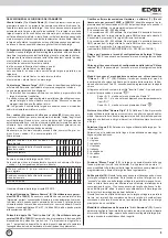
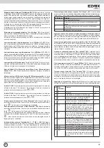
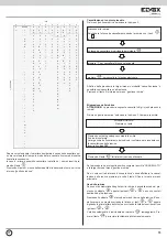
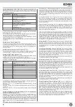
Submenu
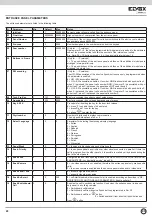
PARAMETERS
This menu provides access to the entrance
panel operating parameters
KEYCODES
This menu is used to program the keys inser-
table from keypad
HW - SW ASSOC.
From this menu, which is only visible if the SW
encoding parameter (par. 07) is different from 0,
and therefore if HW – SW association is enabled,
it is possible to associate the hardware code of
direct call push-buttons (optional) with a software
number which will be used to make the call.
TIME BANDS
Time bands are programmed from this menu
STORE
TRANSPONDER
Transponder keys are programmed from this
menu.
DEL.TRANSPON-
DER
From this menu it is possible to delete tran-
sponder keys which have already been inserted
individually.
ERASE KEYS
From this menu it is possible to completely erase
the key database, from keypad or from transpon-
der.
To delete the keys it is necessary to enter code
321.
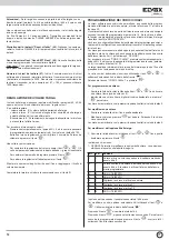
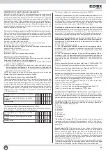
PROGRAMMING ENTRANCE PANEL TECHNICAL PA-
RAMETERS
The entrance panel is delivered with the technical parameters initialised
with the default value. If the value of one or more parameters needs to be
modified, it is possible to:
1. Access the entrance panel parameters from the “PARAMETERS” menu
on the entrance panel;
2. Use a computer and the “ANALYZER” software type 94CD to connect
to the entrance panel with interface type 6952 or 6952/A
ACCESSING THE ENTRANCE PANEL PARAMETER MENU
To access the entrance panel setup menus, simultaneously press push-but-
tons R + 4 and enter the technical programming password (parameter 8).
The default value is 123.
The entrance panel initially displays the firmware version then after 10 se-
conds or when a button is pressed it enters the setup menu.
The various submenu items can be scrolled using the “
” and “
” but-
tons. The selectable submenu is indicated by the “
” arrow.
Select the “PARAMETERS” item and press
.
After programming has been completed, connect the entrance panel to the
system by connecting the digital signal wire to connector terminal 1.
PROGRAMMING WITH “ANALYZER”
For programming with the “ANALYZER” software, refer to the instructions
supplied with the product.
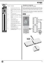
With the entrance panel switched off, connect interface type 6952 or 6952/A
to terminals 1 4 of the connector on the entrance panel. If multiple entrance
panels are connected in parallel, the entrance panel can be programmed
while still connected to the system if a code has been assigned to the en-
trance panel (“entrance panel code” parameter) and by setting the same
value in the Analyzer Digibus address. Otherwise, if using Digibus address
= 0, the entrance panel must be isolated from the rest of the system by
disconnecting the digital signal wire which goes from terminal 1 to the inter-
phone riser and to the other entrance panels.
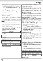
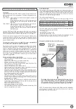
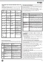
THE PANEL SETUP MENUS
To access the entrance panel setup menus, simultaneously press push-but-
tons R + 4 and enter the technical programming password (parameter 8),
the default value is 123.
The entrance panel initially displays the firmware version then after 10 se-
conds or when a button is pressed it enters the setup menu.
The various submenu items can be scrolled using the “
” and “
” but-
tons. The selectable submenu is indicated by the “
” arrow.
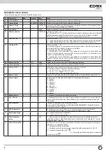
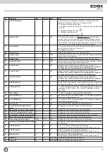
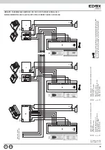
The selectable submenus are:
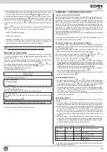
But-
ton
Setup parameter
Function
“
”
Par. 47 1st quick number
Calls the stored number
(if users are present in the
agenda)
Access user agenda
“
”
Par. 19 Enable switchbo-
ard call = 2
Send call to main switchboard
Par. 48 2nd quick number
Calls the stored number
(if users are present in the
agenda)
Access user agenda
“
”
(if users are present in the
agenda)
Access user agenda in search
mode
“
0
+
”
INSERT KEY
If configured by par.10 “Key 0-R1-
C” enables the keycode to be in-
serted
“
”
INSERT KEY
If configured by par.10 “Key 0-R1-
C” enables the keycode to be in-
serted
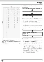
BUTTON
C O M B I N A -
TION
PAS-
SWORD
MENU
ACTION
R
+
1
Programmed
in keys
INSERT KEY
If configured by
par.10 “Key 0-R1-C”
enables the keycode
to be inserted
R
+
2
ABC
Programmed
in par. 45
“F1 code”
INSERT F1
CODE
Activates function F1
R
+
3
DEF
Programmed
in par. 46
“F2 code”
INSERT F2
CODE
Activates function F2
R
+
4
GHI
123 (default)
PROGRAM-
MING
Enables access to
the entrance panel
setup menu
R
+
5
JKL
123 (default)
VOLUME
CONTROL
Accesses the menu
for volume control
with call in progress
R
+
6
MNO
1234
MEASURE-
MENTS
Displays the mea-
surements taken by
the entrance panel
on the bus
R
+
7
PQRS
222 (default)
AGENDA
SETUP
Enables access to
the agenda pro-
gramming menu.
R
+
9
WXYZ
None
DATALOGGER
If enabled by para-
meter 30, accesses
the datalogger menu
R
+
1
+
2
ABC
+
3
DEF
(or)
1
+
2
ABC
+
3
DEF
None
SOFTWARE
VERSION
D i s p l a y s t h e
software version of
the entrance panel
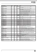
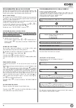
PROCEDURE FOR ACCESSING ENTRANCE PANEL FUN-
CTIONS
Simultaneously press two or more buttons to access the entrance panel
submenus listed in the following table:
(the simultaneous pressing of the buttons is indicated by the symbol “+”,
for example R+1 indicates the simultaneous pressing of buttons R and 1)
.
QUICK FUNCTION BUTTONS
When the entrance panel is displaying the main menu, certain buttons are
used to access quick functions. The functions are listed below in order of
priority.
EN


