33
EN
IT
12
0
PRI
12
0
PRI
P
L
L
P
L
P
J1
C
J1
C
J1
C
5
4
3
2
1
R1
R2
4
4
S1
15
0
PRI
F2
CH
S
F1
4
35
12345
134
1
3
4
5
5
CH
+L
M1
V2
+I
SR
V1
VL
F1
4
F2
CH
V
3
1
M
5
8
6
4
+L
M1
V2
+I
SR
V1
VL
F1
4
F2
CH
V
3
1
M
5
8
6
4
+L
M1
V2
+I
SR
V1
VL
F1
4
F2
CH
V
3
1
M
5
8
6
4
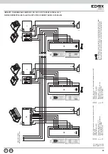
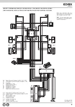
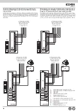
IMPIANTO CONDOMINIALE SEMPLICE CON DUE O PIÙ TARGHE IN PARALLELO
SIMPLE RESIDENTIAL INSTALLATION WITH TWO OR MORE PANELS IN PARALLEL.
Rif. schema si030
Ref. diagram si030
Per la disattivazione del generatore di corrente tagliare il ponticello metal-
lico “J1” posizionato sul retro (in basso a destra) dell’unità elettronica.
Disconnect the metal jumper located on the side of the terminal block.
Montante citofoni
Interphone cable riser
Rete
Mains
Rete
Mains
Rete
Mains
F2
TT
Q1
Q1
C0 -
Audio electronic unit with keypad and display Art. 1282
CX -
Entrance panel
F2 -
Power supply Art. 6941
L -
Electric lock 12V A.C.
P -
Additional push-button for lock
T -
Transformer Art. M832
Q1 -
Relay Art. 0170/001
C0 -
Unità elettronica audio con tastiera e display Art. 1282
CX -
Targa audio
F2 -
Alimentatore Art. 6941
L -
Serratura elettrica 12V A.C.
P -
Pulsante supplementare serratura
T -
Trasformatore Art. M832
Q1 -
Relè Art. 0170/001
CX
1
23
456
789
0
ABC
DEF
GHI
J
KL
MNO
PQRS
TUV
WXYZ
.,;
R
CANC
CX
1
23
456
789
0
ABC
DEF
GHI
J
KL
MNO
PQRS
TUV
WXYZ
.,;
R
CANC
CX
1
23
456
789
0
ABC
DEF
GHI
J
KL
MNO
PQRS
TUV
W
XYZ
.,;
R
CANC
C0
C0
C0

