I
1300
10/20
INSTALLAZIONE DELLE TARGHE DA INCASSO PARETE
-
Installare a muro la scatola da incasso
(L)
ad una altezza di circa 1,65m
dal bordo superiore dalla scatola al pavimento
Nota:
Le targhe della serie 1300 possono essere ampliate
solo in senso orizzontale con targhe supplementari, unendo le scatole
da incasso per mezzo degli appositi agganci forniti con le scatole (vedi
fig. 3).
-
Nel caso di impianto citofonico: fissare la staffetta
(C)
nella parte alta
del telaio
(B)
per mezzo delle viti, nei fori predisposti e fissare il posto
esterno alla staffetta (vedi fig.10, 12)
-
Nel caso di impianto videocitofonico: fissare la telecamera
(I)
al telaio
(B)
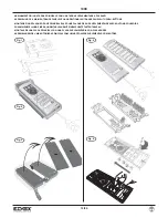
come indicato nelle fig. 1, 11, 13
-
Sfilare o tagliare il tappo in gomma (preesistente nei posti esterni audio
o telecamere) facendo attenzione a non tagliare i cavi del microfono
(vedi fig.7) e inserire il microfono nell’apposita sede posta sul telaio
(B)
richiudendo il tappo come indicato nella fig. 7 part. 1
-
Fissare i pulsanti
(G)
al telaio
(B)
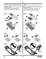
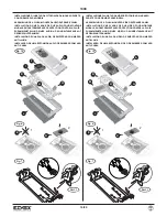
come indicato nelle fig. 10, 11, 12, 13
-
Fissare la scheda per illuminazione a LED
(H)
nell’apposita sede come
indicato nelle fig. 10, 11, 12, 13
-
Fissare l’eventuale cornice parapioggia
(M)
alla scatola da incasso
-
Fissare il telaio alla scatola da incasso o alla cornice parapioggia
-
Nel caso di impianto citofonico sul retro della placca frontale si deve: to-
gliere l’anello per obiettivo
“E”
e inserire la mascherina di chiusura
obiettivo
“D”
(vedi fig. 6)
-
Nel caso di impianto videocitofonico sul retro della placca frontale si
deve: togliere la mascherina di chiusura obiettivo
“D”
e inserire l’anello
per obiettivo
“E”
(vedi fig. 6)
-
Nel caso di placche audio/video art. 1321, 1331, per aumentare i tasti
esterni, togliere i moduli copriforo e i tasti, nell’ordine dal basso verso
l’alto (vedi fig. 5), e poi inserire i tasti esterni R131 (o R131/10), nell’or-
dine inverso, dall’alto verso il basso. Nel caso di placche supplementari
art. 1358, 1372, per diminuire i tasti esterni, seguire la medesima pro-
cedura usando i moduli copriforo art. R130 (o R130/10).
-
Collegare all’impianto posto esterno/telecamera, pulsanti e LED.
-
Chiudere la targa fissandola al telaio per mezzo di un cacciavite (vedi fig.
2)
INSTALLAZIONE DELLE TARGHE DA ESTERNO PARETE
-
Installare a muro la scatola da esterno parete
(N)
ad una altezza di circa
1,65m dal bordo superiore della scatola al pavimento.
Nota:
Le targhe della serie 1300 possono essere ampliate solo in senso
orizzontale con targhe supplementari
-
Nel caso di impianto citofonico: fissare la staffetta
(C)
nella parte alta
del telaio
(B)
per mezzo delle viti, nei fori predisposti e fissare il posto
esterno alla staffetta (vedi fig. 14)
-
Nel caso di impianto videocitofonico: fissare la telecamera
(I)
al telaio
(B)
come indicato in fig. 1, 15.
-
Sfilare o tagliare il tappo in gomma (preesistente nei posti esterni audio
o telecamere) facendo attenzione a non tagliare i cavi del microfono
(vedi fig.7) e inserire la capsula microfonica nell’apposita sede posta sul
telaio
(B)
richiudendo il tappo come indicato nella fig. 7 part. 1
-
Fissare i pulsanti
(G)
al telaio
(B)
come indicato nelle fig. 14, 15
-
Fissare il telaio alla scatola da esterno
-
Fissare la scheda per illuminazione a LED
(H)
nell’apposita sede come
indicato nelle fig. 14, 15
-
Nel caso di targa con solo posto esterno audio sul retro della placca
frontale si deve: togliere l’anello per obiettivo
“E”
e inserire la masche-
rina di chiusura obiettivo
“D”
(vedi fig. 6)
-
Nel caso di targa con telecamera sul retro della placca frontale si deve:
togliere la mascherina di chiusura obiettivo
“D”
e inserire l’anello per
obiettivo
“E”
e (vedi fig. 6)
-
Nel caso di placche audio/video art. 1321, 1331, per aumentare i tasti
esterni, togliere i moduli copriforo e i tasti, nell’ordine dal basso verso
l’alto (vedi fig. 5), e poi inserire i tasti esterni R131 (o R131/10), nell’or-
dine inverso, dall’alto verso il basso. Nel caso di placche supplementari
art. 1358, 1372, per diminuire i tasti esterni, seguire la medesima pro-
cedura usando i moduli copriforo art. R130 (o R130/10).
-
Collegare all’impianto, posto esterno/telecamera, pulsanti e LED.
-
Chiudere la targa fissandola al telaio per mezzo di un cacciavite (vedi fig.
2)
FLUSH-MOUNTED PANEL INSTALLATION
-
Install the flush-mounted box (L) on the wall at a height of approx. 1.65
m from the top edge of the boxes to the floor.
Note:
The entrance panels of the 1300 series can only be extended ho-
rizontally with supplementary entrance panels by joining the flush-
mounted boxes with the hooks supplied with the boxes to fasten them
together (see fig. 3).
- For audio door entry systems: secure the bracket
(C)
at the top of the
frame
(B)
by means of the screws in the prearranged holes and fix the
speech unit to the bracket (see fig. 10, 12).
-
For video door entry systems: secure the video camera
(I)
to the frame
(B)
as shown in fig. 1, 11, 13.
-
Extract or cut the rubber plug (already existing in the audio speech units
or video cameras) taking care not to cut the cables of the microphone
(see fig. 7) and insert the microphone into the seat on the frame
(B)
clo-
sing the plug as shown in fig. 7 detail 1.
-
Secure the push-buttons
(G)
to the frame
(B)
as shown in fig. 10,11, 12,
13.
-
Secure the LED lighting card
(H)
in the seat as shown in fig. 10,11, 12,
13.
-
Secure any rainproof cover
(M)
to the flush-mounted box.
Secure the frame to the flush-mounted box or to the rainproof cover.
-
For audio door entry systems on the back of the front plate it is neces-
sary to: remove the ring for lens
“E”
and insert the cover closing the
lens
“D”
(see fig. 6)
-
For video door entry systems on the back of the front plate it is neces-
sary to: remove the cover closing the lens
“D”
and insert the ring for
lens
“E”
(see fig. 6).
-
In the case of audio/video plates type 1321, 1331, to increase the num-
ber of external keys, remove the blanking modules and the keys in order
from bottom to top (see fig. 5), and then insert external keys R131 (or
R131/10) in reverse order, from top to bottom. In the case of additional
plates type 1358, 1372, to reduce the number of external keys, follow
the same procedure using blanking modules type R130 (or R130/10).
-
Connect the speech unit/video camera, pushbuttons and LEDs to the
system.
-
Close the entrance panel by securing it to the frame with the aid of a
screwdriver (see fig. 2)
SURFACE WALL-MOUNTED PANEL INSTALLATION
-
Install the surface wall-mounted box (N) on the wall at a height of ap-
prox. 1.65 m from the top edge of the boxes to the floor.
Note:
The entrance panels of the 1300 series can only be extended ho-
rizontally with supplementary entrance panels
-
For audio door entry systems: secure the bracket
(C)
at the top of the
frame
(B)
by means of the screws in the prearranged holes and fix the
speech unit to the bracket (see fig. 14)
-
For video door entry systems: secure the video camera
(I)
to the frame
(B)
as shown in fig. 1, 15.
-
Extract or cut the rubber plug (already existing in the audio speech units
or video cameras) taking care not to cut the cables of the microphone
(see fig. 7) and insert the microphone capsule into the seat on the frame
(B)
closing the plug as shown in fig. 7 detail 1.
-
Secure the push-buttons
(G)
to the frame
(B)
as shown in fig. 14, 15.
-
Secure the frame to the surface wall-mounted box.
-
Secure the LED lighting card
(H)
in the seat as shown in Fig. 14, 15.
-
For audio door entry systems on the back of the front plate it is neces-
sary to: remove the ring for lens
“E”
and insert the cover closing the
lens
“D”
(see fig. 6)
-
For video door entry systems on the back of the front plate it is neces-
sary to: remove the cover closing the lens
“D”
and insert the ring for
lens
“E”
(see fig. 6)
-
In the case of audio/video plates type 1321, 1331, to increase the num-
ber of external keys, remove the blanking modules and the keys in order
from bottom to top (see fig. 5), and then insert external keys R131 (or
R131/10) in reverse order, from top to bottom. In the case of additional
plates type 1358, 1372, to reduce the number of external keys, follow
the same procedure using blanking modules type R130 (or R130/10).
-
Connect the speech unit/video camera, pushbuttons and LEDs to the
system.
-
Close the entrance panel by securing it to the frame with the aid of a
screwdriver (see fig. 2)
GB
Summary of Contents for 1300 Series
Page 19: ...1300 19 20 ...


