19
1C 2C
2B
1A
1B
2A
2 1
1
2
1 2
2D
1D
1
E+
FP
E-
2
M
CH
+12
+I
+U
-
PRI
1 2
K
K
DISTRIBUTORE
DISTRIBUTOR
MONITOR
MONTANTE
IN
POWER SUPPLY
ALIMENTATORE
RETE
MAINS
2
2
1
1
12V
CH
FP
M
E-
E+
MONITOR
OUT
MONTANTE
FP
E-
M
1
E+
2
CH
+12
K
FP
E-
M
1
E+
2
CH
+12
K
Cavo
All’Alimentatore
CH
1
1 2
2
E+
E-
FP
M
+12
1 2
CH
1
2
E+
E-
FP
M
+12
AL2
CH
1
2
E+
E-
FP
M
+12
PRI
AL1
M
- +U
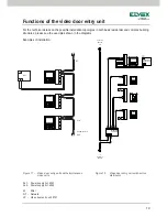
Functions of the video door entry unit
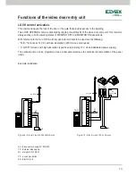
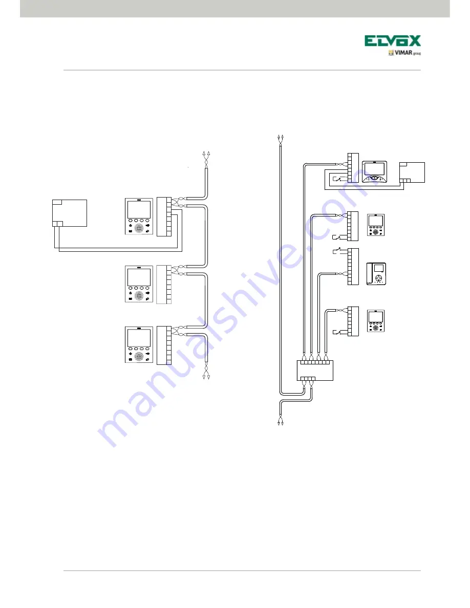
For the technical details on the possible installation topologies in both basic residential and complex building
structures, please see the examples shown in the diagrams.
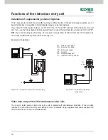
Examples of installation:
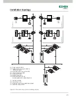
Figure 17 - Video door entry units with simultaneous
video calls
AL1 - Power supply Art. 6923
AL2 - Power supply Art. 6922
M - Pillar
NT - Network
VV - Video door entry unit 5721
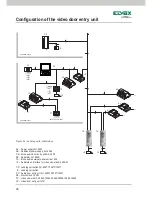
Figure 18 - Video door entry units with active
distributor

