background image

31

Confi guration of the video door entry unit

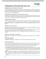
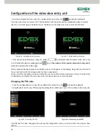
• On tapping the softkey 

(corresponding to the icon 

 ) you adjust the volume with the softkeys 

B

 and 

C


(icon 

 ). 

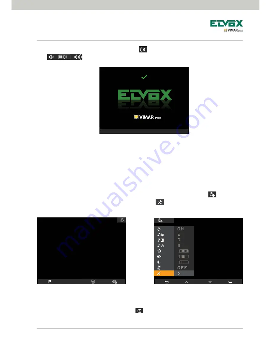
The ID number is then saved by the video door entry unit and is shown in green at the top of the display (fig. 
30).  To view the screen wait for the end of the timeout of 4 seconds.    

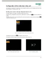
Accessing the configuration menu.

The Configuration menu is used to carry out all the operations for changing the ID of the video door entry unit, 
setting the functions and associating the related icons, configuring the intercom calls, setting the PIN code, etc. 
• To access the Configuration menu, starting from the main screen, tap the softkey 

D

 (icon 

 ). 

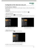
The Settings menu is displayed; using 

B

 and 

select the icon 

 and tap the softkey 

D

The video door entry unit now asks you to enter the PIN 

000

 that is the default set in the factory.  

•  Using 

B

 and 

enter 000 and tap the softkey 

D

 to confirm each one of the numbers entered (fig. 34).

Tapping the softkey 

A

 (corresponding to the icon 

 ) deletes the current number so as to be able to set 

it again.  

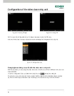
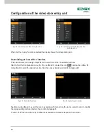
Figure 30 - Initialization performed

Figure 32 - Settings menu

Figure 31 - Main screen

Summary of Contents for 5721

Page 1: ...Installer Manual Art 5721 5721 D Video door entry unit with 3 5 monitor for Due Fili Two Wire call system Elvox Vimar Group ...

Page 2: ......

Page 3: ...Configuring the standard functions of the video door entry unit 24 Enabling the Self Start function 24 Enabling the User Away function 24 Landing calls audio only 24 Landing calls audio video 25 Audio video interface for video cameras 27 Switching on the video door entry unit for the first time 30 Accessing the configuration menu 31 Changing associating a new ID with the video door entry unit 32 S...

Page 4: ...2 Indice Resetting configurations 62 Integrating the video door entry unit with the By me system 63 Installation rules and regulatory compliance 63 Glossary 64 ...

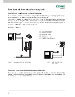
Page 5: ... as regards the type of cables to be used for connecting system components both toward the pillar and toward the speech unit it is recommended to use the 2 wire twisted non polarized type with a cross section of 1 mm art 732H for indoor installations If laying underground in drainage channels or in environments where regulations require using LSZH or LS0Z cables you must use cable art 732I In the ...

Page 6: ...ual users needs Main technical characteristics of the system All the system elements are connected via bus with 2 wires that are twisted and not polarized Up to a total of 200 users comprising audio and video door entry units Up to 15 entrance panels audio and video Recommended cable art 732H for indoor installation art 732I for underground installation with drainage channel art LSZH or LS0Z or a ...

Page 7: ... Fili Two Wire range in particular the following items are recommended 6922 basic video door entry unit power supply 6923 additional power supply for entrance panels and monitors 6852 power supply for additional video cameras 692S separator for the division of conversation areas 692C concentrator for connections of up to 4 entrance panels of which at least one is a video door entry version 69AM au...

Page 8: ...t can be programmed for different functions according to the needs of each user The digital relay must always be associated with its own ID address Technical characteristics 3 0 4 0 c m 3 0 4 0 c m Hearing aid function art 5721 D only Art 5721 D has an internal coil which allows hearing aid wearers to use the device For an effective magnetic coupling between the monitor and the hearing aid it is a...

Page 9: ...TRICAL LOCK of the gate F Button for SELF STARTING the panel and CYCLIC VIEWING of the images transmitted by the video cameras of the video door entry system H HANDSFREE ANSWER button to answer the call end the call end self start display the intercom call user menu confirm the recipient user and end the intercom call A B C D Buttons to access the setup and configuration menus of the video door en...

Page 10: ...he back of the video door entry unit and near the 8 pin terminal block must be set according to the instructions given in Fig 3 and in the following table Position A No termination If the bus enters and exits the device Position B Termination 100 Ω If the bus terminates in the device Position C Termination 50 Ω If the bus terminates in the device ON 1 2 ON 1 2 ON 1 2 ON 1 2 Figure 3 Selecting the ...

Page 11: ...configuration and programming of the system follow this procedure in sequence Install and connect all the devices to the system In the case of a video door entry system set the dip switches for the video termination as shown in the video termination selection table page alongside When there are electronic entrance panels with push buttons do the hardware programming of any push button modules In s...

Page 12: ... please see the technical documentation for the panel used On the bottom bar there are icons associated with the corresponding softkeys of the video door entry unit in particular icon softkey A The function of the button varies depending on the type of save made If just one function is saved tapping A will activate the function If more than one function is saved up to 16 tapping A displays the dro...

Page 13: ...nce panels can be programmed as a panel param eter using the PC interface 692I U and EVCom software The self start on further additional stand alone CCTV type video cameras for instance 20560 19560 14560 20565 19565 14565 is constrained by the presence of the audio video interface 02016 For more details see the AUDIO VIDEO INTERFACE FOR VIDEO CAMERAS chapter in this manual Confidential Conversatio...

Page 14: ...at a door or gate has remained open this application is useful for example to signal any unwanted entry into the dwelling To enable this function you must connect a sensor with N O contacts to terminals PA and M of the panel in the Due Fili Two Wire system N B When the door is closed the sensor must be in the N O state Example installation Figure 8 Connection of the door open signal TE External vi...

Page 15: ...ing states of MONITOR OFF and MONITOR ON respectively With reference to the Due Fili Two Wire panel its terminals to be used are the following S S for locks at 12 V dc with low absorption 200 mA max continuous 12V SR for locks with high absorption specific external relay 12 V dc and dedicated power supply The activation time can be programmed as a panel parameter see the technical documentation of...

Page 16: ...is control is always active in both operating states of MONITOR OFF and MONITOR ON respectively To activate you can use the AUX SERVICE commands up to a max of 16 independent services with the support of an external digital relay art 69RH 69PH The command is activated by tapping the associated softkey that sends the AUX 1 SERVICE command that activates the corresponding output in the supporting di...

Page 17: ...d 6 A AC1 You can use the AUX SERVICE 1 2 commands with the support of an external digital relay art 69RH or 69PH The activation time of the AUX SERVICES 1 16 can be set directly from the relay for full details please see the documentation for art 69RH or 69PH Doorbell calls This application enables with a normal N O button outside and connected directly to the video door entry unit accomplishing ...

Page 18: ...h unit is made with the call button 20577 or 19577 or 14577 while the audio video speech unit is made of the same call button which is combined with a video camera art 20560 19560 14560 or 20565 19565 14565 with the possibility of adding also the LED illuminators art 20570 19570 14570 if the ambient light is not sufficient Finally to make the audio video call from the landing it is necessary to us...

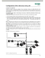
Page 19: ... C D PRI AL2 IF A B C A V Functions of the video door entry unit Figure 14 Landing calls audio video For further details on the connections see the technical documentation of the single articles call button video cameras etc and the related diagrams given therein AL1 Power supply Art 6922 AL2 Power supply Art 6852 IF Audio video interface for video cameras Art 69AM SP Separator Art 692S CP Landing...

Page 20: ...inals of the video door entry unit and if you use the Elvox ringtone 860A powered from the mains the terminals to be wired are CH and M N B If you are not using external relays do not exceed a power draw of 100 mA from the 12 output so as not to cause malfunctioning of the video door entry unit Examples of installation Video door entry units with simultaneous video calls The need to install severa...

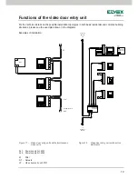
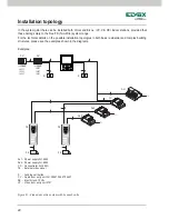
Page 21: ... E FP M 12 AL2 CH 1 2 E E FP M 12 PRI AL1 M U Functions of the video door entry unit For the technical details on the possible installation topologies in both basic residential and complex building structures please see the examples shown in the diagrams Examples of installation Figure 17 Video door entry units with simultaneous video calls AL1 Power supply Art 6923 AL2 Power supply Art 6922 M Pil...

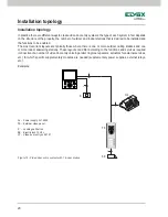
Page 22: ...bled The most recurrent layouts are typically those where there is one or more outdoor calling stations and one or more indoor answering stations These layouts can differ according to the functions and services required connection of a number of video door entry units in parallel ringtone repeaters actuators for external services etc for which specific supplementary modules are needed supplementar...

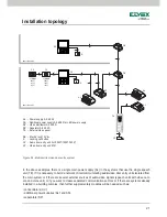
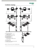
Page 23: ... or if there are several external sources of audio video signals speech units with video cam era and voice unit or if you want to create separated communication sectors or if there are systems already installed in a building complex then further supplementary modules will be needed such as concentrators CC additional power supplies AL1 and AS separators SP AL Power supply Art 6922 AS Additional po...

Page 24: ...re system range For the technical details on the possible installation topologies in both basic residential and complex building structures please see the examples shown in the diagrams Examples Figure 21 Video door entry system with 2 speech units AL1 Power supply Art 6922 AL2 Power supply Art 6923 CC Concentrator Art 692C TE External video panel K Landing call button CV Audio door entry unit Art...

Page 25: ...allation topology Figure 22 Video door entry system in a building complex AL Power supply Art 6922 AS Additional power supply Art 6582 for LED power supply CE Elvox audio door entry unit Art 6209 DV Video distributor Art 692D SP Separator Art 692S TE External video panel VE Elvox video door entry unit Art 6029 6209 6145 6029 6209 6145 K Landing call button SE Electric lock 12 Vdc CV Audio door ent...

Page 26: ...try unit that receives the call doesn t emit any audible warning and it doesn t turn on the monitor The entrance panel will beep and in the case of alphanumeric panels with a display it will show the away message Audio video communication for landing calls If there is the need to install one or more indoor audio video call stations landing call there are two different types landing calls audio onl...

Page 27: ... audio door entry unit with the landing call button 20577 19577 14577 using the PC and the USB interface 692I U with EVCom software see the chapter called CONFIGURATION OF THE OPTIONAL FUNCTIONS OF THE VIDEO DOOR ENTRY UNIT Associating landing calls in this manual N B To associate the video audio door entry unit with the landing call of the audio video type it is necessary to keep the call type se...

Page 28: ...io door entry unit Art 6209 SP Separator Art 692S TA Elvox audio external panel series 1300 IF Audio video interface for video cameras Art 69AM CP Landing call button Art 20577 19577 14577 K Landing call button CV Audio door entry unit Art 20557 19557 14557 SE Electric lock 12 Vdc TC Video camera Art 20560 19560 14560 20565 19565 14565 VV Video door entry unit 5721 Figure 24 Landing calls audio vi...

Page 29: ... only associated with the landing call button 20577 19577 or 14577 the video cameras corresponding to the calls sent from the landing buttons maximum 4 landing calls with the related video camera can be turned on and self start is also possible on the various video cameras connected to the interface making a fictitious intercom call toward the call button APPLICATIONS 1 Using the interface 69AM fo...

Page 30: ...as with audio Art 69AM CC Concentrator Art 692C TV External video panel NT Network PA Door opening command SE Electric lock 12 V DC TC CCTV camera 12 VDC Figure 26 Example of installation of additional video cameras Configuration of the video door entry unit N B For each video door entry unit it is possible to configure the self start sequence of the additional video cameras connected to the audio...

Page 31: ...r video cameras 02016 therefore it is necessary to use the PC and the USB interface 692I U with the EVCom software see the related technical documentation On sending the audio video call by pressing the landing nameplate button art 20577 19577 or 14577 the interface will enable the video camera associated with it With this type of configuration it is possible to connect up to 4 video cameras for t...

Page 32: ...y unit are now in audio communication to assign the latter s ID useful timeout 30 s If the panel has push buttons press the button that you want to associate with the video door entry unit if instead the panel is alphanumerical key in the number to associate and press button On completing initialization the monitor will show the screen in fig 30 Tapping the softkey A corresponding to the icon stop...

Page 33: ...nit setting the functions and associating the related icons configuring the intercom calls setting the PIN code etc To access the Configuration menu starting from the main screen tap the softkey D icon The Settings menu is displayed using B and C select the icon and tap the softkey D The video door entry unit now asks you to enter the PIN 000 that is the default set in the factory Using B and C en...

Page 34: ...entry unit with a new ID that is different to the one previ ously associated From the Configuration menu use B and C to select the icon and tap the softkey D The video door entry unit enters into communication with the panel and the initialization phase is started fig 36 in a similar way as illustrated in par Switching on the video door entry unit for the first time Figure 35 Configuration menu Fi...

Page 35: ...re saved functions Figure 38 Main screen with 1 saved function Secondary ID coding for the video door entry unit Programming the secondary identification code is only required when you want to have more than one video door entry unit ring at the same time with the same push button or call code The video door entry units that must ring at the same time are associated with the same group It is possi...

Page 36: ...nel and the initialization phase is started fig 40 in a similar way as illustrated in par Switching on the video door entry unit for the first time If the panel has push buttons press the button associated with the master video door entry unit if instead the panel is alphanumerical key in the number of the master video door entry unit to associate and press the button If the procedure has taken pl...

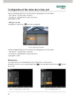
Page 37: ... landing intercom call To set these ringtones starting from the main screen fig 31 tap the softkey D icon Setting the panel call tune Using B and C select the icon and confirm by tapping D Using B and C select the desired tune 10 tunes available identified with the letters from A through J and confirm by tapping D Setting the landing call tune Using B and C select the icon and confirm by tapping D...
Page 38: ...try unit starting from the main screen tap the softkey D icon and using B and C select the icon then tap D to confirm Using the softkeys B and C select the icon ringtone disabled lastly tap D to confirm Note When finished at the upper right corner the display will show the icon CAUTION In the event of a video door entry call the monitor will be activated but you will not hear a ringtone The ringto...

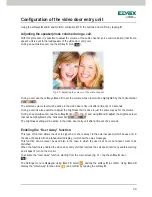
Page 39: ...ontal bar short pressure single increase or decrease long pressure gradually faster increase or decrease Lastly tap D to confirm Setting the video parameters This menu is used to set the brightness and contrast for optimal viewing of the image on the display To set these parameters starting from the main screen tap the softkey D icon Setting the brightness Using B and C select the icon and confirm...

Page 40: ... level which will be highlighted by the horizontal bar short pressure single increase or decrease long pressure gradually faster increase or decrease Lastly tap D to confirm Button tones This option allows you to enable disable the tone emitted when you tap the buttons Starting from the main screen tap the softkey D icon and using B and C select the icon then tap D to confirm Configuration of the ...

Page 41: ...s level that will be highlighted by the horizontal bar The brightness setting will be active in the video door entry unit after a timeout of 2 seconds Enabling the User Away function This type of function allows the user to signal he or she is away via the external panel which beeps and in the case of panels with an alphanumeric display it will show the away message This function can moreover be u...

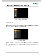
Page 42: ...vailable and confirm by tapping D Tap D and using B and C select the icon to associate with the function the icon is useful in order to identify the corresponding command better then confirm by tapping D The icon tells the video door entry unit that the associated command corresponds to a function Fig 58 Available functions Fig 59 Selecting a function Fig 56 Accessing the User Away function Fig 57...

Page 43: ...icon and tap the softkey D Using B and C select the function to edit and confirm by tapping D Tap D and using B and C select the new icon to associate with the selected function then confirm by tapping D The video door entry unit will save the new association overwriting the previous one no confirmation message will be displayed Fig 61 List of functions Fig 60 Selecting the identification icon ...

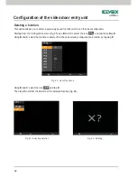
Page 44: ...tion which can then be reconfigured Starting from the Configuration menu fig 35 use B and C to select the icon and tap the softkey D Using B and C select the function to delete from the ones already configured and confirm by tapping D Using B and C select the icon and tap D Then tap D to confirm the deletion of the selected function fig 64 Fig 62 List of functions ...

Page 45: ... that you want to be involved in the intercom call fig 66 To do this simply press the LOCK button softkey G in the case of an art 5721 of the video door entry unit that you want to associate with the intercom call fig 67 For example if you are configuring an intercom call in the lounge video door entry unit and you want it to involve the video door entry unit installed in the kitchen you need to t...

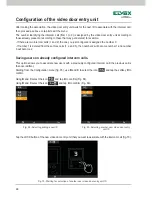
Page 46: ...d number 3 will become 2 Saving users on already configured intercom calls This option allows you to associate new users with a previously configured intercom call the previous call is then overwritten Starting from the Configuration menu fig 35 use B and C to select the icon and tap the softkey D to confirm Using B and C select the icon and tap D to confirm Fig 68 Using B and C select the icon an...

Page 47: ...ion menu fig 35 use B and C to select the icon and tap the softkey D to confirm Using B and C select the icon corresponding to the video door entry unit you want to delete for example and tap D to confirm Fig 71 Using B and C select the icon and tap D to confirm Fig 72 Then tap D to confirm the deletion of the selected video door entry unit Fig 73 Configuration of the video door entry unit Fig 71 ...

Page 48: ...e monitor will show the screens of fig 75 or 76 and it will not then be possible to send commands options and will however remain active Once the condition of Bus busy has ended the video door entry unit will again be able to send commands to all the other devices in the system Configuration of the video door entry unit Fig 74 Call from consumer unit waiting Fig 75 The galvanic isolation BUS is bu...

Page 49: ...Enables FUNCTIONS F1 F2 for panels 1 8 Consumer unit Enables control via the consumer unit F9 16 G3 External only Enables Group 3 only for external calls from panel G4 Internal only Enables Group 4 only for intercom calls Do not beep Disables the beep when a button is pressed No RIPCH IC Disables intercom call repetition G1 External only Enables Group 1 only for external calls from panel G2 Intern...

Page 50: ...48 Fig 77 Configuration of the video door entry unit ...

Page 51: ...ng In the former instance they are used to send a lock opening command self start and send a stair light activation command In the latter instance the functions can be modified using the listbox in the Buttons menu highlighted in the figure 78 Table 2 lists the functions and a description of the reconfigured setting in relation to the default Fig 78 Configuration of the video door entry unit ...

Page 52: ...nel NO INT CALL Activates and deactivates the intercom call When selected intercom calls cannot be made to the monitor NO EXT CALL Activates and deactivates the entrance panel call When selected intercom calls can not be made from the entrance panel to the monitor LOCK GEN The general button becomes like the Lock button in default mode Applies to Lock self start stair light buttons Applies from ve...

Page 53: ...e section Activating P Function to activate the P functions and the corresponding relays configured previously Icon assignment from the P Menu is illustrated in figure 80 To open the list of icons as illustrated by the arrow Example if a command is sent to P2 relay AUX2 will be activated with ID 0 see table Fig 79 Configuration of the video door entry unit Function Function Relay ID P1 AUX1 ID0 P2...

Page 54: ...eferring to the activated functions will appear in the Buttons menu figure 81 RELAY 1 RELAY 5 in the example image NOTE for information regarding ID assignment please refer to the relay product instruction manual Fig 80 Fig 81 Configuration of the video door entry unit ...

Page 55: ...the Buttons menu and P menu if for example P2 is modified in the Buttons menu with F1 assigned to it an icon must be assigned to P2 in the P menu FUNCTION DESCRIPTION FREE No function assigned for buttons P1 to P6 F1 Activation of function F1 for the current or last entrance panel connected F1 PANEL Activation of function F1 for a specific entrance panel The ID number should be entered in the box ...

Page 56: ...54 Fig 83 Configuration of the video door entry unit ...

Page 57: ...s functions and ID codes to be configured on the 69PH products are listed in the table For detailed information regarding ID assignment please refer to the 69PH relay product instructions Fig 84 Configuration of the video door entry unit Function Function Relay Relay ID P7 AUX 7 RL 7 ID3 P8 AUX 8 RL 8 P9 AUX 9 RL 9 ID4 P10 AUX 10 RL 10 P11 AUX 11 RL 11 ID5 P12 AUX 12 RL 12 P13 AUX 13 RL 13 ID6 P14...

Page 58: ...nitor can be programmed with a list of 9 intercom calls A tenth is added automatically if the porter switchboard Art 945F is part of the system Calls are indicated with progressive numbers from 1 to 9 Neither the ID nor an alphabetic indication is displayed at the user s end ...

Page 59: ...ry unit Reset PIN code If the default PIN code 000 is changed and forgotten it will no longer be possible to configure the monitor using its keyboard and display Select this check box to force restoring of the PIN to its default value which is 000 ...

Page 60: ...ifferent groups G1 G2 G3 and G4 Each device can be associated with one group indicating the identification code of the master in the fillable fields When the master receives a call depending on the programming the other devices in the Group will also be activated or they will ring without activation Group Calls ...

Page 61: ...s is used to assign the ID of the landing call buttons from which the video door entry unit can receive a call indicating it in the fillable fields Each video door entry unit can be configured to receive up to 4 different calls from the landing call buttons Associating Landing Calls ...

Page 62: ...cally It is also possible to vary and set the volume for each ringtone Example of setting ringtones with EVCom Ringtone Identifier Description Ringtone 0 A Trill Ringtone 1 B Muffled trill intermediate pause Ringtone 2 C Bright trill short pause Ringtone 3 D Muffled trill medium pause Ringtone 4 E Telephone trill Ringtone 5 F Muffled trill long pause Ringtone 6 G Ding dong Ringtone 7 H Bright ding...

Page 63: ...meters This is used to set the video adjustment levels brightness and contrast of the monitor of the video door entry unit Example of brightness and contrast adjustment with EVCom N B For all the details about using the EVCom software see the relevant manual Video Adjustments ...

Page 64: ...gramming done on the video door entry unit and bring it back to the initial default operating conditions Starting from the Configuration menu fig 35 use B and C to select the icon and tap the softkey D to confirm fig 91 Lastly tap D to confirm the reset operation fig 92 Fig 91 Selecting the Reset option Fig 92 Confirming Reset ...

Page 65: ...utomation system the appliance will be in home auto mation mode and will switch onto video door entry mode every time there is an external call or when the user activates it via the navigation menus on the By me home automation side Integrating the home automation module 01965 requires using a supplementary power supply art 6923 Installation rules Installation should be carried out in compliance w...

Page 66: ...ackbones derived from a column interface or a speech unit interface Shunt Two wire line coming out of a distributor or divider to which the indoor stations are connected Termination Impedance which must be configured by using the jumpers or dip switches It enables keeping the characteristic impedance of the pillar or shunt Power supply Device that incorporates the drives for lock opening the call ...

Page 67: ...panels of the system are identified with an ID other than 1 Basic programming Programming the main functions of a device Generally this programming can be done without the aid of addi tional instruments such as programmers or PCs some settings can be made directly by the user Advanced programming Programming the optional functions of a device done only by the installer with the aid of additional t...

Page 68: ...S6I 572 12E RL 00 1304 ELVOX Campodarsego Italy Via Pontarola 14 a 35011 Campodarsego PD Italy Tel 39 049 920 2511 Fax 39 049 920 2603 http www elvox com ...

Reviews: