15
EN
V
7
3
2
1
5
4
6
10
9
8
12
11
13
M
2
C
A
6S
6E
6P
6
3
5
7
AU
1
CN1
V1
5
3
2
1
4
10
8
6
7
9
V3
13
M
11
12
V2
1 2 3 -
S
6 7 8 - +T AM 15 O S1
+
C1
PRI
M1 V1 V2 M2
AU C2
A
B
CN2
A
M1
V2
V1
M2
C2
B
AU
1
PRI
+
3
2
-
S
6
+T
8
7
-
AM 15 0
C1
S1
S1 C1
0
AM 15
+T
8 -
7
6
S
+
3
2
-
AU C2
V2 M2
V1
M1
1
PRI
B
A
Power supply
type 6680/C17
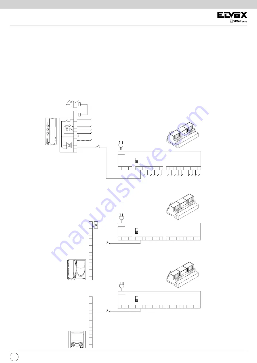
STANDARD VIDEO DOOR ENTRY SYSTEM WIRING DIAGRAM VERSIONS WITH COAX CABLE
VARIATION 7
Wiring diagram for landing call button.
When the landing call push-button is pressed, the monitor sounds with a different tone from the tone generated by a call from the entrance
panel. The monitor remains OFF.
Monitor
type 6300
type 6301
type 6320
type 6321
type 6303
type 6401
type 6500
type 6501
A
Mains
Interphone
type 6200
Monitor
type 6000
type 6003
If type 6150 is installed inside interphone type 6200, the landing call cannot be used.
Mains
A
A- Landing call push-button
Mains
A
Power supply
type 6680/C17
Power supply
type 6680/C17
Monitor
type 6600
type 6700
type 660A


