22
EN
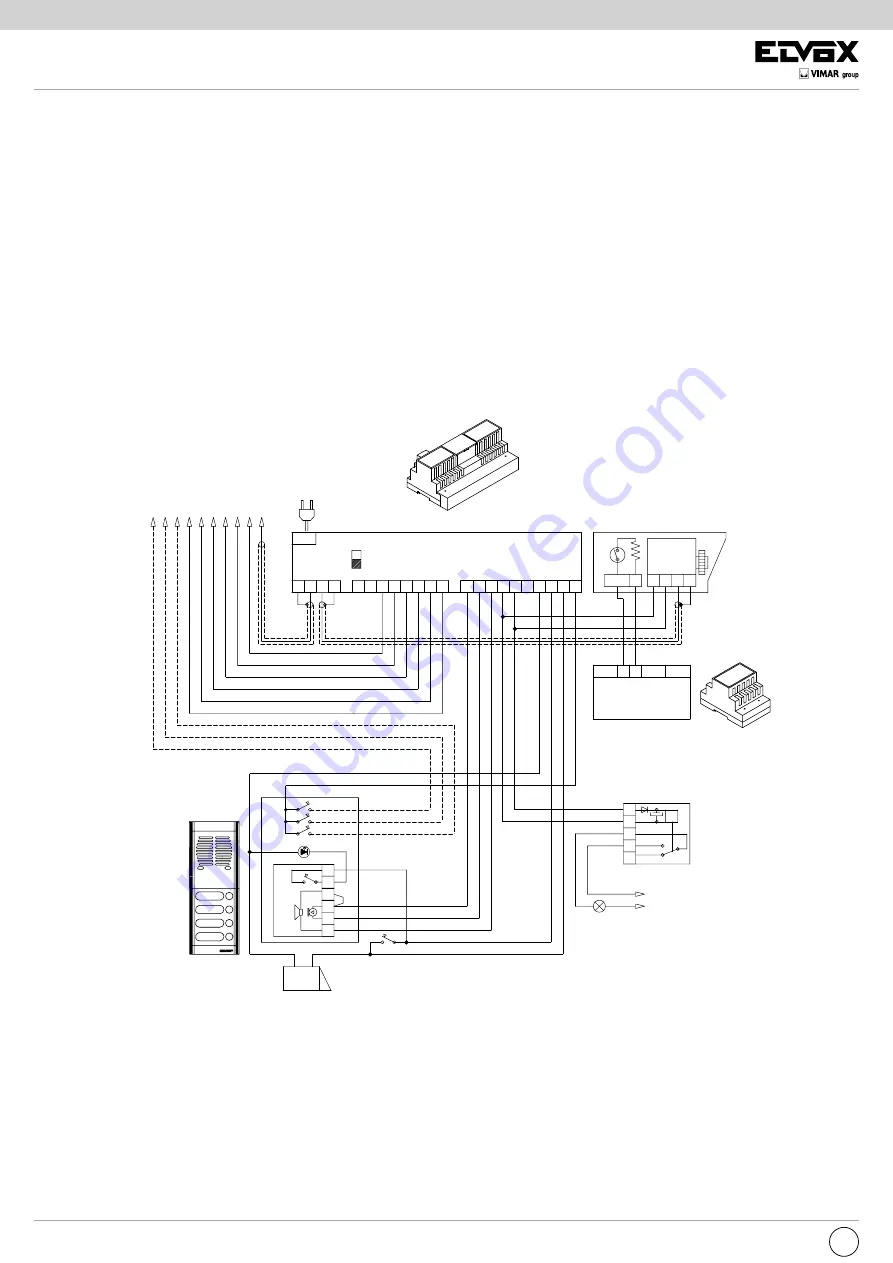
STANDARD VIDEO DOOR ENTRY SYSTEM WIRING DIAGRAM VERSIONS WITH COAX CABLE
VERSION 16
Wiring diagram for the separate camera from the entrance panel with speech unit and additional bulbs for lighting the coverage
area.
R
24 O
PRI
B
A
PRI
B
C
L1
6
8
7
D
3
4
4
5
3
1
2
2
CH
CH
CH
3
5
6
9
6
C2
AU
M2
V2
V1
M1
+ S
3
2
1
V
1
-
C1
S1
O
15
AM
+T
8
7
-
O
T
24
- +T V M
A
5
A- 8100, 1200, 3300, 8000, PATAVIUM, or letter box
2550/302-302 series audio entrance panel
B- Additional door lock button
C- Electric lock 12V AC
D- Speech unit type 930 or 930A
L1- Led module for entrance panel
(10 module LED max.)
30 module LED con Art. M832
40 module LED con Art. 832/030
Relay
type 0170/001
Maximum load
3A - 230V
Power supply
type 6680/C17
Mains
Additional camera with
waterproof housing
type 5000-5020-5A20-5B20
type 5A10-5B10-5C10
AC mains
power supply
Illumination bulb
coverage area.
For B/W filming, you can use
series 5250 infrared bulbs
MONITOR CABLE RISER
It is possible to connect an entrance panel with the speech unit only and a separate camera type 5000 - 5020 - 5A20 - 5B20 - 5A10
-5B10-5C10. The illumination bulb must be inserted as shown in the diagram.
The illuminated push-button connected to terminals 3 and 4 of the speech unit type 930 or 930A can be used to switch the entrance panel
illumination bulbs on momentarily, as shown in the diagram.
Transformer
type 832/024
Mains


