24
EN
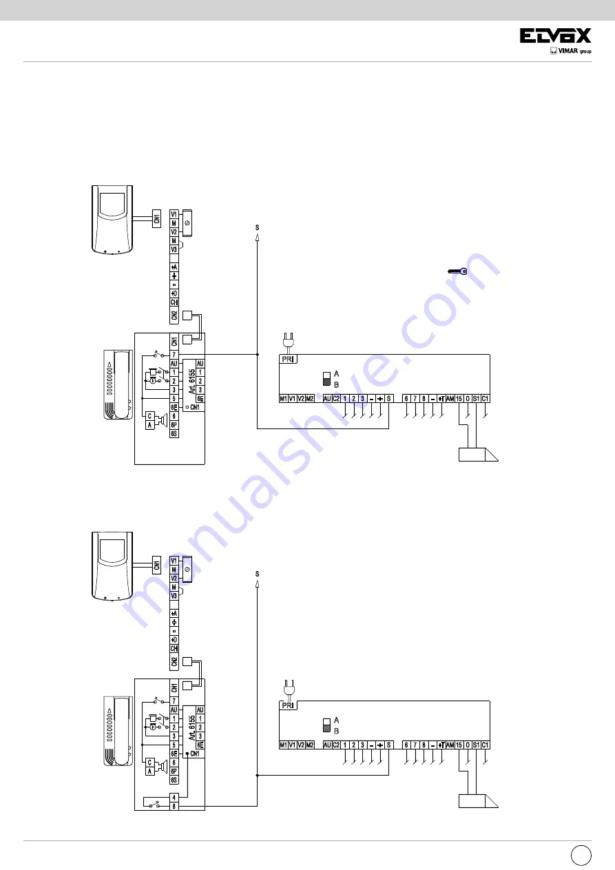
STANDARD VIDEO DOOR ENTRY SYSTEM WIRING DIAGRAM VERSIONS WITH COAX CABLE
VERSION 18
Wiring diagram of video entry unit with conversation privacy and door lock release after call.
To provide conversation privacy, fit card type 6155 into interphone type 6200.
V3
CH
CN2
+
+D
-
+A
CN1
V1
V2
M
M
V1
CN1
-
CH
CN2
+D
V3
+
+A
V2
M
M
Art. 615
5
Art. 6155
PRI
7
6
C
6S
A
6P
AU
2
6E
5
3
1
AU
6E
2
3
CN1
1
M1
CN1
S
M2
V1 V2
1 2
AU C2
B
A
S
+
3 -
7 8
6
AM 15
- +T
C1
O S1
7
AU
2
1
6E
3
6S
4
8
C
A
6
6E
5
6P
CN1
AU
2
1
3
CN1
S
+
PRI
M1
V2
V1
M2
C2
AU
1
B
A
3
2
-
S
6
8
7
-
O
AM
+T
15
C1
S1
Power supply
type 6680/C17
Mains
12 V A.C. electric
door lock.
Interphone
type 6200 + 6155
Power supply
type 6680/C17
Mains
12 V A.C. electric
door lock.
Interphone
type 6200 + 6155 + 6152
Monitor
type 6000
type 6003
Interphone
type 6000
type 6003
Use the push-button with the symbol
, connected as
shown in the diagram, to enable opening of the door lock
at any time.
Use additional push-button N. 1, connected as shown
in the diagram, to enable opening of the door lock
after a call, with the interphone ON.


