25
EN
A
B
M1 V1 V2 M2
AU C2 1 2 3 - + S
6 7 8 - +T AM 15 0 S1 C1
PRI
PRI
0 15
3
4
6
7
8
CT
+T
V
M
C
D
B
A
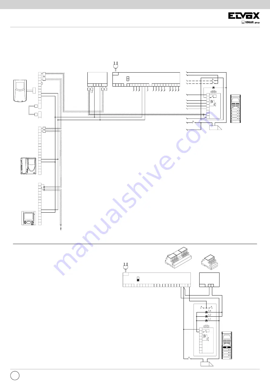
VERSION 20
Wiring diagram for transformer type M832-832/030 in
entrance panels with name tag illumination bulbs
The transformer is used when there are three or more
name tag illumination bulbs.
Mains
POWER SUPPLY
type 6680/C17
Mains
TRANSFORMER
type 832/C17
type 832/3C7
A- Video entrance panel 3300, 8000, 8100, 1200
PATAVIUM series or letter box type 2550/301-302
C - Camera
B - Electric lock 12V~
D- Electric lock button
L1- Led module for entrance panel
(10 module LED max.)
30 module LED con Art. M832
40 module LED con Art. 832/030
7
3
1
2
5
4
6
V
M
11
9
8
10
13
12
V
1
3
2
4
12
8
6
5
7
10
9
11
V1
V3
13
M
V2
CN1
+A
CN1
CH
CN2
+D
+
-
V2
V3
M
M
V1
ELVOX
1 2 3 -
S
6 7 8 - +T AM 15 O S1
+
C1
PRI
M1 V1 V2 M2
AU C2
A
B
L1
B
4
3
6
7
8
M
V
+T
C
CT
A
D
1 2 3 Vout
Vin
75 Oh
m
STANDARD VIDEO DOOR ENTRY SYSTEM WIRING DIAGRAM VERSIONS WITH COAX CABLE
VARIATION 19
Wiring diagram for video amplifier type 5559.
When the connection lines are more than 200 metres long, on video or
CCTV door entry systems, the attenuation of the video signal on the coa-
xial cable makes it necessary to use video line amplifier type 5559. It is
possible, however, to exceed lengths of 200 metres with good quality coa-
xial cable. The amplifier operates with input and output impedances of 75
Ohm; it is therefore advisable to use RG59 coaxial cable or good quality
cables with equivalent impedance. It is advisable to install
the amplifier near the power supply, in a dry, ventilated area. It is possible
to install the amplifier on the monitor cable riser; if you do this, however,
the amplifier will also amplify any disturbance signals on the video con-
nection line. The amplifier is equipped with a device which adapts the gain
to the length of the line.
It is therefore necessary to move the 3-pin connector to the position cor-
responding to the line length nearest to the pre-selected values of 200 m,
400 m, 600 m and 800 m. For intermediate line lengths move the 3-pin
connector to the position corresponding to the length immediately below
the available values; then adjust the gain trimmer P1, until the image has
sufficient contrast. Make the connection as shown in the diagram.
Remember to leave in place the 75 Ohm load resistance to the input ter-
minals “IN”. Connect the resistances supplied with the V2-M terminals of
the last monitor. For the other connections, refer to the wiring diagrams for
the power supply type 6680.
Power supply
type 6680/C17
Mains
Amplifier
type 5559
A- Video entrance panel
8000, 3300, 8100
PATAVIUM series or letter box
type 2550/301-302
C - Camera
type 559, 559A, 559B, 559G, 558, 570,
570G, 571, 559C, 570C
B - Electric lock 12V~
D- Electric lock button
L1- Entrance panel illumination bulb
(3x24V 3W max)
10x24V 3W with type M832
16X24V 3W with type 832/030
Monitor
Type 6000
Type 6003
Monitor
type 6300
type 6500
type 6301
type 6320
type 6321
type 6401
type 6501
Monitor
Type 6600
Type 6700
Type 660A


