33
EN
-
CH
+
+
-
CH
CH
+
-
+
CH
-
+
-
CH
+
CH
-
6
4
2
1
3
5
12
10
9
7
8
11
6
3
1
2
4
5
9
7
8
11
12
10
6
3
2
1
5
4
9
8
7
12
11
10
11
12
10
6
3
1
2
4
5
9
7
8
6
3
1
2
4
5
9
7
8
11
10
12
M
V
13
V
M
13
13
M
V
13
V
M
V
M
13
CH
6
6P
6S
AU
3
5
6E
1
2
CN1
7
CN2
CN1
V3
+
+D
-
+A
V1
M
V2
M
CH
5
6P
6S
6E
6
AU
1
2
3
7
CN1
CN2
V3
+D
+
-
+A
V2
M
V1
M
CH
5
6P
6S
6E
6
AU
1
2
3
7
CN1
CN2
V3
+D
+
-
+A
V2
M
V1
M
CH
5
6P
6S
6E
6
AU
1
2
3
7
CN1
CN2
V3
+D
+
-
+A
V2
M
V1
M
CH
5
6P
6S
6E
6
AU
1
2
3
7
CN1
CN2
V3
+D
+
-
+A
V2
M
V1
M
CH
5
6P
6S
6E
6
AU
1
2
3
7
CN1
CN2
V3
+D
+
-
+A
V2
M
V1
M
12
1
3
2
4
8
6
5
7
10
9
11
M
13
V3
V2
V1
12
12
1
3
2
4
8
6
5
7
10
9
11
1
3
2
4
11
10
8
6
5
7
9
M
V3
13
V1
V2
V1
V3
M
13
V2
12
1
3
4
2
8
7
5
6
11
9
10
M
V3
13
V1
V2
12
1
3
2
4
8
6
5
7
10
9
11
M
13
V3
V2
V1
- +U
+I
B C
A
PRI
1
2
3
CH
- +
S
V
+
1
2
3
-
S
V
C
O
15
CH
6
3
5
6
3
5
PRI
C
+U
-
+I
A B
15
C
O
V
V
3
5 4
2 1
2 1
3
5 4
55 44 33 22 11
PRI
+U
-
C +I
15
A B C
CH
O
V 6 5 3
V 6 5 3
55 44 33 22 11
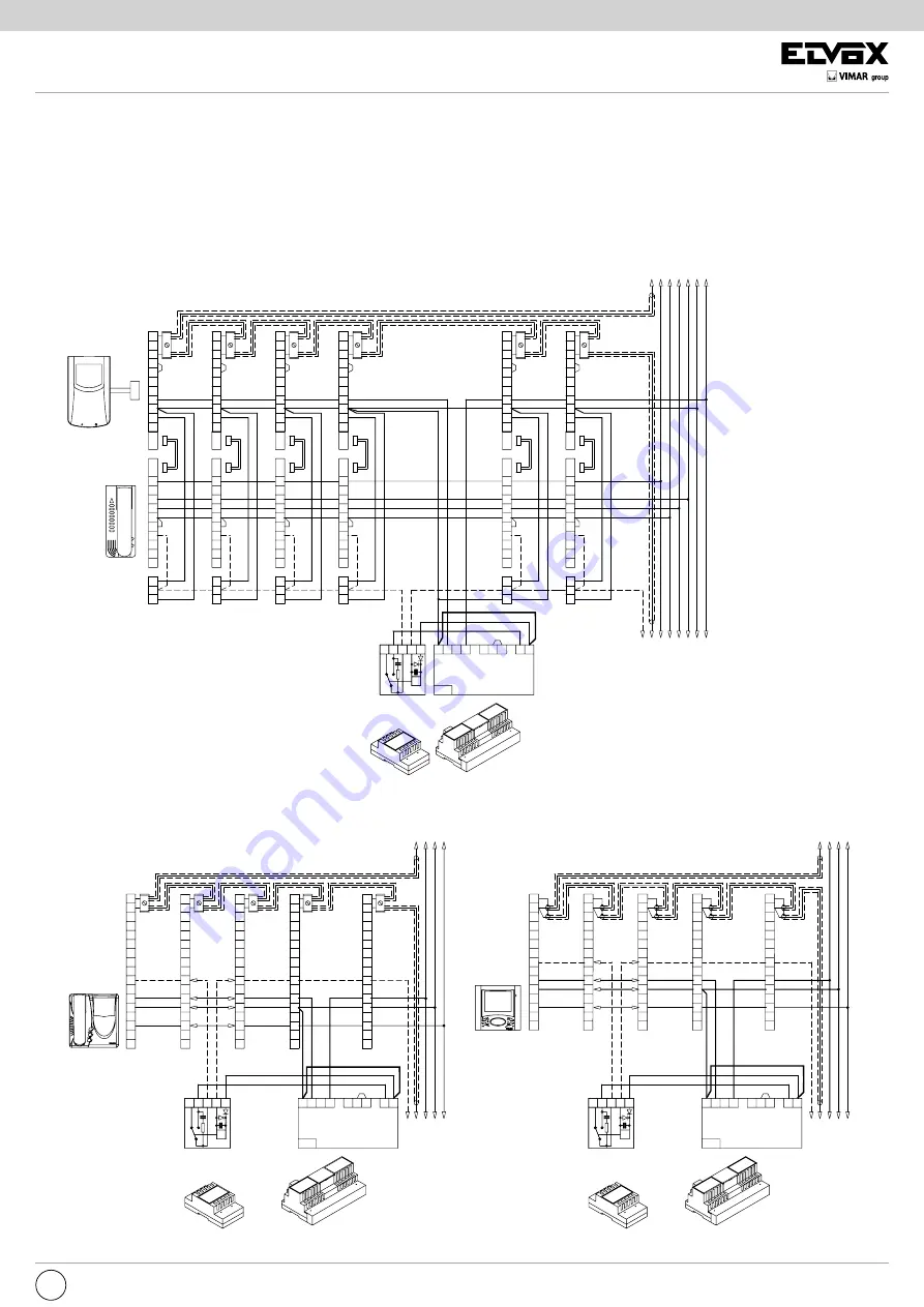
STANDARD VIDEO DOOR ENTRY SYSTEM WIRING DIAGRAM VERSIONS
VARIANTE 1
Wiring diagram for simultaneous activation of two or more monitors by power supply Type6583 .
A single power supply may be connected as shown in the diagram to simultaneously activate two or more monitors. Type6583 can simultaneously power
up to 4 monitors Ty 6200 + 6150 o 6300, 6303, 6500.
N.B.
Set the shunt present on the terminal
block side into “BC” position.
MONITOR
Type 6000 +
Type 6200 +
Type 6150
MONITOR
Type 6003 +
Type 6200 +
Type 6150
MAX 4
MONITOR
MONITOR
Type 6000 +
Type 6200 +
Type 6150
MONITOR
Type 6003 +
Type 6200 +
Type 6150
MAX 2
MONITOR
MONITOR
Type 6300
Type 6320
Type 6303
Type 6500
Relay
Type 0170/001
Power supply
Type 6583
Mains
To power supply
Type 6680
Monitor cable riser
Monitor cable riser
To power supply
Type6680
Power supply
Type6583
Mains
Relay
Type0170/001
Relay
Type0170/001
Power supply
Type6583
Mains
Monitor cable riser
MONITOR
Type 6600
Type 6700
Type 660A


